
Woodward SPM-D2-10B/PSY5-FU-D 8440-2170
Product number: 8440-2170
Manufacturer product number: 8440-2170
Description: Woodward: SPM-D2-10B-PSY5-FU-D, 1ph, 400V, 24Vdc, Switchable Parameter
Predecessor: 8440-1871; 8440-1869
Dead Bus Start (Asynchronous Add-On)
Output of an add-on order for the power circuit breaker (“CB close”) without synchronization, if the following
conditions are fulfilled:
The dead bus start function is in principle activated by configuration
One of the three possible dead bus start functions is selected by configuration
The discrete input "Dead bus start release" is energized
The discrete input "Release CB" is energized
The discrete input "Reply: CB is open" is energized
The conditions for one of the preset dead bus start functions are fulfilled:
a) U1 has the value Un (taking the configured rated voltage difference into account dV |V-Vrated|) and U2 is
zero (taking the configured zero voltage difference into account dV |V-0|).
b) U1 is zero (taking the configured zero voltage difference into account dV |V-0|) and U2 has the value Vrated
(taking the configured rated voltage difference into account dV |V-Vrated|).
c) U1 is zero and U2 is zero (taking each configured zero voltage difference into account dV |V-0|).
Moreover, in case a) and b) the frequency of U1 and U2 must be within the configured limits.
The close command “CB close” is a pulse signal with the duration configured by pulse time (parameter 8933).
With additional “Synch-check” activation (terminal 54) the relay “CB close” remains permanently energized
as long as the dead bus closure conditions are fulfilled.
Synch-Check
In this condition, the unit can be used as a synchronization control. No control is carried out. The relay "CB
close" remains picked up, as long as the following conditions are met:
The voltage differential is within the configured limit
(screen "synchronization dVmax)
The frequency differential is within the configured limit
(screens "synchronization dfmax and dfmin")
The phase angle is within the configured limit
(screen "slip synchron. phimax")
The discrete input "Reply: CB is open" is energized
The discrete input "Enable CB" is energized
The systems U1 and U2 are within the permitted limits
(see Table 5-2: Operating modes - operating conditions, condition A, page 16).
The discrete input “Synch-check” is energized.
Synchronizing pulse:
close CB
Terminals 14/15
Ready for operation
Terminals 18/19
"Message:
Connect 2"
Terminal 16/17
Three-position
controller speed
higher/lower
Terminals 8/9/10
Three-position
controller voltage
higher/lower
Terminals 11/12/13
Through this relay, the CB receives the order to add-on. In normal operation,
the contact assembly in the synchronous point only closes for the configured
time of the add-on pulse. When in synchronizing control mode, a continuous
signal is output through this relay (see chapter "Control Inputs" on page 17).
If the CB has made contact and the unit gets this information through a corre
sponding discrete input, this relay de-energizes.
The contact assembly is closed when the unit is ready for operation. The relay
will de-energize if the following occurs:
a) The internal self-monitoring system has detected an alarm condition.
Trouble-free operation of the unit cannot be guaranteed and appropriate
corrective measures must be taken.
b) The synchronization time monitoring system is enabled and the config
ured time has expired before synchronization has occurred.
For the description of these control inputs please refer to chapter "Relay Out
put 16-17" on page 37
Through these relays, pulses are output from the internal speed governor, in
order to adjust the frequency of system U2 to the frequency of system U1
(synchronization), or to adjust the frequency to the configured set point fre
quency (no-load control). In order to obtain the speed variation required, the
relays have to be connected with the appropriate inputs of an external speed
governor. The order "lower" is output through the terminals 8/10. the order
"higher" is output through the terminals 8/9.
Through these relays, pulses are output from the internal speed governor, in
order to adjust the voltage of system U2 to the voltage of system U1 (syn
chronization), or to adjust the voltage to the configured voltage set point (no
load control). In order to obtain the voltage variation required, the relays have
to be connected with the appropriate inputs of an external voltage controller.
The order "lower" is output through the terminals 11/13. the order "higher"
through the terminals 11/12.
| GE | IC800SS1228R02-CE |
| GE | FS16 |
| GE | IC687BEM731 |
| GE | MPU55 |
| GE | IC695CHS016-CA |
| GE | IC695PSD140A |
| GE | IC200CHS022E |
| GE | IC693CMM321-JJ |
| GE | IC694ACC310A |
| GE | QPJ-SBR-201 |
| GE | F650NFLF2G5HIP6E |
| GE | VMIVME 2540-300 |
| GE | VMIVME 3215-000 |
| GE | VMIVME 4140-000 |
| GE | IC660HHM501 |
| GE | 369-HI-R-0-0-0-0-E |
| GE | IS200AEADH4A 109W3660P001 |
| GE MULTILIN | MTM |
| User name | Member Level | Quantity | Specification | Purchase Date |
|---|


-
 IBA ibaNet-E
 -
 IBA FO Connection to Reflective Memory
 -
 IBA FO Connection to Siemens Systems
 -
 IBA Interface Cards For Fiber Optic Connections
 -
 IBA Field and Drive Buses
 -
 IBA ibaPADU-S Modular System
 -
 IBA ibaMAQS
 -
 STUCKE SYMAP®ARC
 -
 STUCKE SYMAP®R
 -
 STUCKE SYMAP®Compact
 -
 MOOG G123-825-001 BUFFER AMPLIFIER
 -
 Motorola MVME5100 Series VME Processor Modules
 -
 Motorola MVME162 Embedded Controller
 -
 HIMatrix Safety-Related Controller System Manual for the Modular Systems
 -
 Motorola MVME2400 Series VME Processor Module
 -
 Sieger System 57
 -
 KONGSBERG MRU product line continuation
 -
 Woodward easYgen-3100/3200 Genset Control for Multiple Unit Operation
 -
 Woodward MFR 300 Multifunction Relay / Measuring
 -
 ABB AX410, AX411, AX413, AX416, AX418, AX450, AX455 and AX456 Single and dual input analyzers for low level conductivity
 -
 ABB AX410, AX411, AX416, AX450 and AX455 Single and dual input analyzers
 -
 Woodward easYgen-1400 Technical Manual Genset Control
 -
 Woodward easYgen-400 Operation Manual Genset Control
 -
 Woodward High Output Digital Valve Positioner (DVP)DVP5000/DVP10000/DVP12000
 -
 Woodward High Output Digital Valve Positioner DVP5000 and DVP10000
 -
 Woodward TG611-13/-17 Overspeed Test Device Conversion Kit
 -
 Woodward MicroNet Safety Module (MSM)
 -
 Woodward 2301A Electronic Load Sharing and Speed Control 9905/9907 Series
 -
 Woodward-Service Bulletin 01671
 -
 UniOP eTOP40B 12.1” TFT color display
 -
 UniOP eTOP40 TFT Color display
 -
 UniOP eTOP33B 10.4” TFT color display
 -
 UniOP eTOP33C eTOP33-0050 Resistive touchscreen
 -
UniOP eTOP30. eTOP32 eTOP32-0050 Human-machine interface equipment
-
 UniOP eTOP20B and eTOP21B eTOP20B-0050
 -
 UniOP eTOP12 eTOP12-0050 Advanced human-machine interface equipment
 -
 UniOP eTOP11 eTOP11-0050 HMI
 -
 UniOP eTOP06C HMI
 -
 UniOP eTOP06 HMI
 -
 UniOP eTOP05EB eTOP05EB-DF45 HMI
 -
 UniOP eTOP05. eTOP05P Human-machine interface equipment
 -
 UniOP eTOP03 eTOP03-0046
 -
 UniOP eTOP507 507U2P1 eTOP Series 500 Human-Machine Interface
 -
 UniOP eTOP307
 -
 UniOP ETT-VGA Human-machine interface touch unit
 -
 UniOP ePAD32B, ePAD33B and ePAD33BT ePAD33B-0350
 -
 UniOP ePAD05 and ePAD06
 -
 UniOP CP02R-04 Human-machine interface
 -
 UniOP ERT-16 - Industrial PLC Workstation
 -
 UniOP ePAD03 and ePAD04
 -
 UNIOP EPALM10-DA71 state-of-the-art handheld HMI
 -
 Watlow SERIES CLS200 SPECIFICATION SHEET
 -
 Detailed Explanation of B&R Power Panel 300/400: The Core of Industrial Automation Control
 -
 YOKOGAWA Models ANB10S, ANB10D, ANR10S, ANR10D Node Units (for FIO)
 -
 Woodward ESDR 4 Current Differential Protection Relay
 -
 Woodward easYgen-3000 Genset Control for
 -
 Woodward CPC-II Current-to-Pressure Converter
 -
 Woodward 8290-189-EPG-installation-manual 8290-044
 -
 Woodward Product Change Notification 06946A
 -
 Woodward Product Change Notification 06912
 -
 Fisher™ 4660 High-Low Pressure Pilot
 -
 Flexible digital protection and control equipment SYMAP®
 -
 Woodward 723PLUS Digital Control
 -
 Woodward 505 Digital Controller For steam turbineses
 -
 Woodward 85018V2 505E Digital Governor for Extraction Steam Turbines
 -
Woodward 85018V1 Turbine Control Parameters
-
Woodward 26871 505 Enhanced Digital Control for Steam Turbines
-
 Woodward 03365 505E (Extraction / Admission)
 -
 KONGSBERG RMP420-Remote Multipurpose Input/Output
 -
 KONGSBERG RCU501 Remote Controller Unit
 -
 KONGSBERG RCU500 Remote Controller Unit
 -
 K-Gauge TOP KONGSBERG Tank Overfill Protection SystemFeatures
 -
 Kongsberg DPS112 DGNSS (DGPS/DGLONASS) sensor
 -
 Kongsberg d0000930-presafe-atex-report signed
 -
 HIMax TECHNICAL FACTS X Series
 -
 GE Multilin F650
 -
 GE MIF II - Legacy
 -
 GE PQM II Power QualIty Meter
 -
 Hydran 201Ti Mark IV Essential DGA monitoring for transformers
 -
 alstom AMS42/84 5B Amplifier SystemAmplifier Technology at its Best.
 -
 GE VMIVME-5576 Fiber-Optic Reflective Memory with Interrupts
 -
 GE Multilin 750/760 - Legacy Feeder Protection System
 -
 GE Fanuc Automation VMICPCI-7806 Specifications
 -
 VMIVME-7807 VME-7807RC* Intel® Pentium® M-Based VME SBC
 -
 GE Fanuc Automation VMIVME-7750 Specifications
 -
 FOXBORO Compact FBM240. Redundant with Readback, Discrete
 -
 FOXBORO FBM208/b, Redundant with Readback, 0 to 20 mA I/O Module
 -
 FOXBORO FBM201e Analog Input (0 to 20 mA) Interface Modules
 -
 Foxboro DCS FBM206 Pulse Input Module
 -
 FOXBORO FBM216 HART® Communication Redundant Input Interface Module
 -
 FOXBORO Z-Module Control Processor 270 (ZCP270)
 -
 FOXBORO Fieldbus Communications Module, FCM10Ef
 -
 FOXBORO Fieldbus Communications Module, FCM10E
 -
 Foxboro DCS Compact FBM241/c/d, Redundant, Discrete I/O Modules
 -
Foxboro FBM223 PROFIBUS-DP™ Communication Interface Module
-
 Foxboro DCS FBM204. 0 to 20 mAI/OModule
 -
Foxboro FBM239, Discrete 16DI/16DO Module
-
Foxboro FBM202 Thermocouple/mV Input Module
-
 Foxboro E69F Current-to-Pneumatic Signal Converter
 -
 EMERSON M-series Intrinsically Safe I/O
 -
 MVME6100 Series VMEbus Single-Board Computer
 -
 Configuration for AMS 6500 Protection Monitors
 -
 Ovation™ Controller Model OCR1100 (5X00481G04/5X00226G04)
 -
 ABB UCU-22, UCU-23 andUCU-24control units
 -
 ABB force measurement
 -
 AEROTECH Ndrive MP Hardware Manual
 -
 AEROTECH Ndrive HPe 10/20/30
 -
 AEROTECH Ndrive CP Hardware Manual
 -
 AEROTECH Ndrive Linear Series Digital Servo Amplifiers – Linear
 -
 AEROTECH Ndrive HP 10/20/30 P/N: EDU170
 -
 AEROTECH EDU176_Ndrive_HL
 -
 ADVANCEDMOTION CONTROLS Analog Servo Drive 120A10
 -
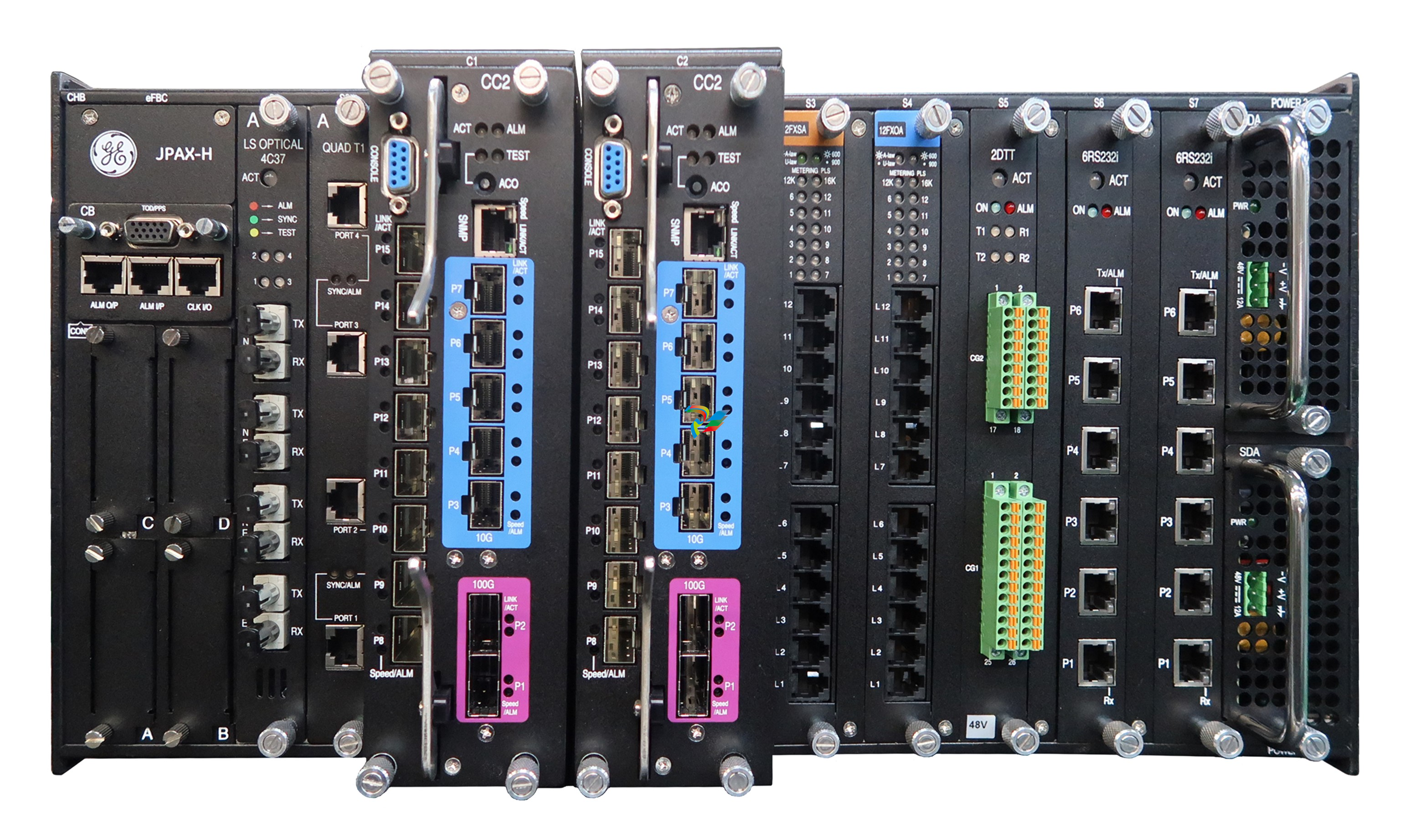 GE JPAX-H
 -
 GE JPAX family
 -
 GE Industry Leading Experience
 -
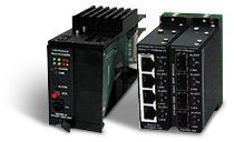 GE Ether-1000 Unit
 -
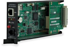 GE Cyber Secured Service Unit
 -
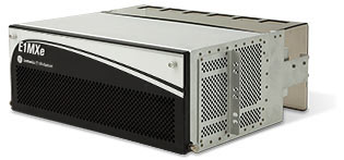 GE Lentronics E1MXe Multiplexer
 -
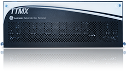 GE TTMX Teleprotection Terminal
 -
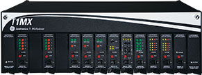 GE Lentronics T1 Multiplexer
 -
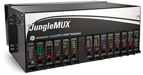 GE Lentronics JungleMUX SONET Multiplexer
 -
 GE Lentronics E1MX Multiplexer
 -
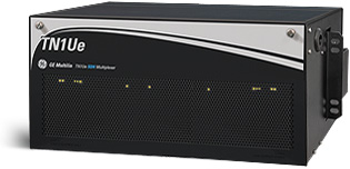
GE Lentronics TN1Ue SDH Multiplexer
-
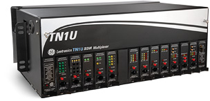 GE Lentronics TN1U SDH Multiplexer
 -
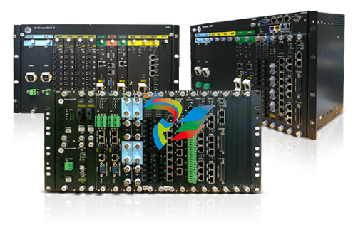 GE Gridcom DXC Family Access and Transmission Multiplexer
 -
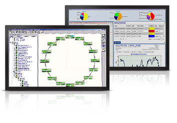 GE Advanced Network Management Simplifying Optical Networks
 -
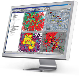
 GE Lentronics VistaNET Network Management System (NMS)
 -
 ABB System Controller Connect


