
schneider140 DDO 885 00
Overview
The DC Output 24 ... 125 VDC 2x6 Source module switches 24 ... 125 VDC powered
loads and is for use with shared ouput common wired to 0 V.
Diagnostic
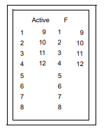
The following table shows the LED indicators for the 140 DDO 885 00 module:
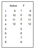
The following table shows the LED descriptions for the 140 DDO 885 00 module:
Notes :
To clear an error indication, the point must be commanded OFF in user logic.
LEDs Color Indication when ON
Active Green Bus communication is present.
F Red An over current condition on any point has been detected.
1 ... 12 Green The indicated point or channel is turned ON.
.. 12 Red The indicated output point has an over current condition.
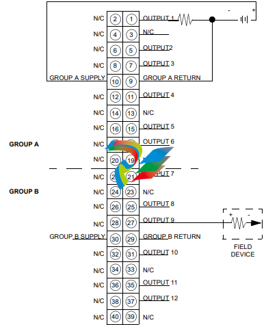
External Wiring Recommendation
1. When field wiring the I/O module, the maximum wire size that should be used is
1-14 AWG or 2-16 AWG; the minimum size is 20 AWG.
2. N / C = Not connected
WARNING
RISK OF EQUIPMENT DAMAGE
This module is not protected against overloads. Respect the output load instructions
in the Hardware Reference Guide (reference: 35010516):
• Peak load current 4 A for t ≤ 1 ms
• Derating chart
Failure to follow these instructions can result in death, serious injury or
equipment damage.
CAUTION
DAMAGE TO MODULE OUTPUTS
This module is not protected against reverse polarity. Follow these precautions to
avoid equipment damage:
• Do not reverse the polarity of the field power supply.
• To help protect the module against polarity miswiring, add an external diode in
series with each group supply line. This diode must be able to support load current.
Failure to follow these instructions can result in injury or equipment damage.
The following illustration shows the wiring diagram for the 140 DDO 885 00 module:
140 DDO 885 00
Überblick
Das 24-125-VDC-Ausgangsmodul 2x6, positive Logik, schaltet Lasten mit
24-125 V DC und ist für den Einsatz mit an 0 V angeschlossenem gemeinsamen
Ausgangsbezugspotenzial bestimmt.
Diagnose
Die folgende Tabelle enthält die LED-Anzeigen des Moduls 140 DDO 885 00:
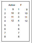
Die folgende Tabelle enthält die Beschreibung der LED-Anzeigen des
Moduls 140 DDO 885 00:
Hinweise:
Um eine Fehleranzeige zu beseitigen, muss der Punkt mittels Benutzerlogik in den
AUS-Zustand gebracht werden.
LEDs Farbe Bedeutung im Zustand EIN
Active Grün Buskommunikation vorhanden.
F Rot Ein Überstromzustand wurde an einem Punkt erkannt.
1 ... 12 Grün Der angezeigte Punkt oder Kanal ist EINGESCHALTET.
1 ... 12 Rot Der angezeigte Ausgangspunkt weist einen Überstromzustand auf
Empfehlungen für externe Verdrahtung
1. Bei der Feldverdrahtung des E/A-Moduls liegt die maximale Drahtgröße zwischen
1-14 AWG oder 2-16 AWG und die minimale Größe bei 20 AWG.
2. N/C = Nicht angeschlossen.
WARNUNG
GEFAHR VON MATERIALSCHADEN
Dieses Modul ist nicht gegen Überlastung geschützt. Beachten Sie die Anweisungen
zur Ausgangslast im Hardware-Referenzhandbuch (Referenz: 35010516):
• Spitzenlaststrom 4 A für t ≤ 1 ms
• Leistungsminderungsdiagramm
Die Nichtbeachtung dieser Anweisungen kann zu Tod, schwerer
Körperverletzung oder Geräteschäden führen.
BESCHÄDIGUNG DER MODULAUSGÄNGE
Dieses Modul ist nicht gegen Verpolung geschützt. Befolgen Sie diese
Sicherheitsvorkehrungen, um einen Materialschaden zu vermeiden:
• Kehren Sie nicht die Polarität der Feldstromversorgung um.
• Wenn Sie das Modul gegen Verpolung durch falsche Verdrahtung schützen
möchten, schalten Sie eine externe Diode mit jeder Gruppen-Stromversorgung
in Serie. Diese Diode muss für den Laststrom ausgelegt sein.
Die Nichtbeachtung dieser Anweisungen kann zu Körperverletzung oder
Geräteschäden führen.
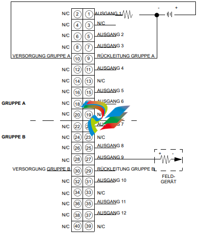
Die folgende Abbildung zeigt das Verdrahtungsschema für das Modul 140 DDO 885 00:
Présentation
Le module de sortie 24 à 125 VCC 2x6 logique positive permet de commuter des
charges de 24 à 125 VCC et doit être utilisé avec un dispositif de sortie commun
partagé relié à la masse (0 V).
Diagnostic
Le tableau ci-dessous présente les voyants du module 140 DDO 885 00 :
Le tableau ci-dessous présente les voyants du module 140 DDO 885 00 :
Remarques :
Pour effacer le signalement d'une erreur, il faut commander la désactivation du point
dans la logique utilisateur.
Voyants Couleur Signification (voyant allumé)
Active Vert La communication avec le bus fonctionne.
F Rouge Une condition de surintensité a été détectée sur un point.
1 à 12 Vert Le point indiqué ou la voie indiquée est activé.
1 à 12 Rouge Le point de sortie indiqué est en surintensité.
Recommandation sur le câblage externe
1. Lors du câblage du module d'E/S, utilisez des câbles d’une dimension maximale
de 1 à 14 AWG ou de 2 à 16 AWG, la dimension minimale étant de 20 AWG.
2. N/C = non connecté.
AVERTISSEMENT
RISQUE DE DETERIORATION DE L'EQUIPEMENT
Ce module n'est pas protégé contre les surcharges. Respectez les instructions sur la
charge en sortie du Guide de référence du matériel (référence : 35010516) :
• Courant de charge en crête 4 A pour t ≤ 1 ms
• Courbe de réduction de charge
Le non-respect de ces consignes peut entraîner la mort, des blessures graves
ou des dommages matériels.
ATTENTION
DETERIORATION DES SORTIES DE MODULE
-
 HIRSCHMANN MSM20-M2M2M2M2SY9HH9E Ethernet media modul
 -
 HIRSCHMANN SPIDER-PL-20-05T1999999TWVHHHH Industrial Ethernet Rail Switch
 -
 Hirschmann SPIDER-PL-20-07T1M2M299TWVHHHH Industrial ETHERNET Rail Switch
 -
.png) Hirschmann (Belden) RS20-1600M2M2SDAEHC09.1.00 DIN-rail managed industrial Fast Ethernet switch
Hirschmann (Belden) RS20-1600M2M2SDAEHC09.1.00 DIN-rail managed industrial Fast Ethernet switch -
 Hirschmann (Belden) RS30-1602O6O6TDAPHC09.1.00 DIN-rail managed industrial Ethernet switch
 -
 Hirschmann (Belden) RS30-2402O6T1SDAPHH09.0.13 DIN-rail industrial Ethernet switch
 -
Hirschmann (Belden) SPIDER-PL-20-04T1S29999TY9HHHH Ethernet DIN-rail switch
-
 HIRSCHMANN RS20-1600T1T1SDAUHX Switch
 -
 HIRSCHMANN BRS42-0012OOOO-SPCZ99HHSES industrial switch
 -
 Hirschmann RS20-0800S2S2TDHPHH09.0.14 Fast Ethernet DIN rail switch.
 -
 HIRSCHMANN MM20-Z6Z6M2M2SAHH Hybrid Fast Ethernet Media Module
 -
 HIRSCHMANN MM20-Z6Z6T1T1SAHH hot-swappable hybrid Fast Ethernet Media Module
 -
 HIRSCHMANN MM20-P9P9T1T1SAHH Hybrid Fast Ethernet Media Module
 -
 HIRSCHMANN MM20-M4T1T1T1SAHH Hybrid Fast Ethernet Media Module
 -
 HIRSCHMANN MM20-M4M4T1T1SAHH Hybrid Fast Ethernet Media Module
 -
 HIRSCHMANN MM20-M2M2M2M2SZHH Ethernet media module
 -
HIRSCHMANN MM20-M2M2M2M2SAHH Ethernet media module
-
 HIRSCHMANN MM20-T1T1T1T1EBH 4-port Fast Ethernet Copper Cable Media Module
 -
HIRSCHMANN MM20-T1T1T1T1SAHH 4-port Fast Ethernet Copper Cable Media Module
-
HIRSCHMANN MM20-T1T1T1T1SAHH 4-port Fast Ethernet Copper Cable Media Module
-
 HIRSCHMANN MM20-Z6Z6EBH Hot-swappable fast Ethernet media module
 -
 HIRSCHMANN MM20-Z6Z6SAHH Ethernet media module
 -
HIRSCHMANN MM20-Z6Z6Z6Z6EBH Industrial Media Module
-
 MSM40-T1T1T1TZ9HH9E99.9.99 HIRSCHMANN Switch
 -
 HIRSCHMANN MS20-0800SAAEHC / MS20-0800SAAEHC0 8-port modular Layer 2 management Ethernet switch
 -
 Hirschmann RSPM20-4T14T1SZ9HHS9 Switch RSPM20-4T14T1SZ9HHS9
 -
 HIRSCHMANN RS20-1600M2M2SDAEHH09.1. RS20/30/40 Managed Switch configurator
 -
HIRSCHMANN RS20-1600M2M2SDAEHX09.0.00 Ethernet switch
-
 HIRSCHMANN BELDEN SPIDER-PL-20-07T1M2M299TY9HHHH / SPIDERPL2007T1M2M299TY9HHHH
 -
HIRSCHMANN MM3-1FXS2/3TX1 Switching Board Module
-
 HIRSCHMANN RSPE30-24044O7T99-ECCP999HHSE2A08.1.00 Industrial-grade fanless management-type Ethernet switch
 -
 HIRSCHMANN RS30-1602OOZZSDAEHC09.1.00 DIN-rail-mounted managed Layer 2 Ethernet switch
 -
 HIRSCHMANN MACH104-20TX-F Managed 24-port Full Gigabit 19" Switch
 -
 HIRSCHMANN Switch RS20-0800M4M4SDAE
 -
Hirschmann RS30-1602O6O6SDAEHH09.1. Management-type Ethernet switch
-
 Hirschmann RS30-1602OOZZSDAEHC09.0.10 Open rack-style Ethernet switch
 -
 HIRSCHMANN RSPE30-24044O7T99-SCCV999HHSI2SXX.X.XX High-Availability Seamless Redundancy
 -
HIRSCHMANN RSPE30-24044O7T99-SCCZ999HHSE2A DIN-rail Ethernet switch
-
HIRSCHMANN MM2-4TX1-EEC switch
-
HIRSCHMANN MSM40-T1T1T1T1TZ9HH9E99.9.99 Module
-
 HIRSCHMANN RS20 Rail Switch RS20-0400S4T1SDAEHC07.1.01
 -
 HIRSCHMANN M4-FAST8-SFP Fast Ethernet media module
 -
 HIRSCHMANN RS20-0400M2T1SDAP Managed Fast-Ethernet-Switch
 -
 HIRSCHMANN BELDEN SPIDER II 8TX/1FX EEC Industrial Ethernet Rail Switch
 -
HIRSCHMANN MM3-2FXS2/2TX1
-
 HIRSCHMANN RS2-4TX/1FX EEC Industrial Ethernet Rail Switch
 -
 RS30-0802O6O6SDAEHC09.0.10 HIRSCHMANN Switch
 -
 HIRSCHMANN m4-8TP-RJ45 Ethernet Media Module
 -
 HIRSCHMANN MSP30-24040SCZ9URHHE3A switch
 -
 Hirschmann rack MS30-1602SAAPHC
 -
 HIRSCHMANN RS2-FX/FX Industrial Switch Module
 -
Rs1txfx - Hirschmann - Rs1-Tx/Fx Rail Switch
-
RS20-0800S2S2SDAEHC09.1.00 HIRSCHMANN Commutator
-
 Hirschmann EAGLE20 TX/TX Industrial Security Router
 -
 Hirschmann SPIDER-SL-20-04T1S29999SY9HHHH Industrial Switch
 -
 HIRSCHMANN MAR1040-4C4C4C4C9999SMMHRHHXX.X. Gigabit Ethernet Switch configurator
 -
 Hirschmann MAR1040 Industrial Switch
 -
 HIRSCHMANN BELDEN RS30-1602O6O6SDAE
 -
Hirschmann RS20-1600M2M2SDAUHC Ethernet DIN rail switch
-
 HIRSCHMANN OCTOPUS 24M industrial switch
 -
 HIRSCHMANN RS20-1600T1T1SDAE Management-type Ethernet switch
 -
 HIRSCHMANN RS20-1600T1T1SDAUHH industrial switch
 -
HIRSCHMANN RS20-0800M2M2SDAPHC09.0.04 switch
-
 Hirschmann MR 8-03 24V DC Industrial Modular Bridge/Router
 -
 HIRSCHMANN RS20-0400M2T1SDAPHC08.0.01 Managed Switch
 -
 MACH1130 Hirschmann Industrial Switch
 -
 HIRSCHMANN 943824-002 SPIDER 5TX Industrial Ethernet Switch
 -
 HIRSCHMANN RS30-0802O6O6SDAEHC09.1.00 Managed Industrial Switch
 -
 HIRSCHMANN RS20-0400M2M2TDAEHC04.0.01 Industrial Switch
 -
 HIRSCHMANN BRS20-0600Z6Z6-STCZ99HHSES Industrial Switch
 -
 HIRSCHMANN MACH104-20TX-FR-L3P Industrial Ethernet Switch
 -
 HIRSCHMANN RS40-0009CCCCEDBPHH06.0.01 Industrial Switch
 -
 HIRSCHMANN RS2-3TX/2FX EEC Industrial Ethernet Switch
 -
 Hirschmann MACH 1020/1030 Fast/Gigabit Rack Mount Switches
 -
HIRSCHMANN RS20-0800M2M2SDAPHC09.0.14 Industrial Switch
-
 HIRSCHMANN RS20-1600T1T1SDAEHC09.0.04 Industrial Switch
 -
 HIRSCHMANN RSB20-0800T1T1EAABHH Industrial Switch
 -
 HIRSCHMANN MACH4002-48+4G-L3E Industrial Backbone Switch
 -
 HIRSCHMANN RS20-0400S2T1SDAE Industrial Managed Switch
 -
HIRSCHMANN RS20-0800S2T1SDAUHC Industrial Switch
-
 HIRSCHMANN RS20-2400S4S4SDAEHC09.0.14 industrial switch
 -
 HIRSCHMANN OS20-001200T5T5T5- TBBZ999HHNE3S 08.1.00 industrial switch
 -
HIRSCHMANN OS20-001200T5T5T5- TBBZ999HHNE3S 08.1.00 industrial switch
-
 HIRSCHMANN RS40-0009CCCCSDAEHH09.0.14 switch
 -
 Hirschmann RS20-1600T1T1SDAUHC Management-type Ethernet Switch
 -
 Hirschmann M1-8SFP Switche
 -
Hirschmann Industrial Ethernet Ruggedized Switch MACH1000 Family
-
 Basler Electric, Solid State Protective Relay, BE1-60
 -
BASLER ELECTRIC SR4A-2B15B3A Static Voltage Regulator
-
.png) BASLER ELECTRIC EXCITER DIODE MONITOR EDM-200
BASLER ELECTRIC EXCITER DIODE MONITOR EDM-200 -
.png) BASLER ELECTRIC DECS125-15-B2C5 DIGITAL EXCITATION CONTROL SYSTEM V 2.0.9
BASLER ELECTRIC DECS125-15-B2C5 DIGITAL EXCITATION CONTROL SYSTEM V 2.0.9 -
 BASLER ELECTRIC BE1-851 OVERCURRENT PROTECTION RELAY MECHANISM
 -
 Basler Electric BE1-51A / BE151A
 -
 Basler Electric BE1-40Q Loss of Excitation Relay
 -
 Basler Electric BE1-87G Variable Percentage Differential Relay
 -
 Basler Electric BE1-11 Protection System I5A3M2P2N0EA00
 -
 BASLER ELECTRIC DECS-200-1C Digital Excitation Control System
 -
 Basler Electric / Kohler BE1-11g Generator Protection Relay G5A3M2J2N0E000
 -
BASLER ELECTRIC DECS125-15 DIGITAL EXCITATION CONTROL SYSTEM
-
 BASLER ELECTRIC BE1-951 OverCurrent Protecton System
 -
Basler Electric DECS-200-1L Digital Excitation Control System
-
 Basler Electric DGC-2020HD-5NS1DNSBA Digital Genset Controller -
 -
 BASLER ELECTRIC BE1-81T1EE1WA0N1F / BE181T1EE1WA0N1F
 -
 BASLER ELECTRIC BE1-25M1EA6PN5R1F / BE125M1EA6PN5R1F
 -
 BASLER ELECTRIC DECS-250-LN1SN1N DIGITAL EXCITATION CONTROL SYSTEM
 -
Basler Electric DECS-250-CN2CN 1N Digital Excitation Control System Unit
-
 BASLER ELECTRIC DECS-300-C0N0 DIGITAL EXCITATION CONTROL SYSTEM
 -
 BASLER ELECTRIC BE1-87T-A1E-A1J-D0S1F / BE187TA1EA1JD0S1F
 -
BASLER ELECTRIC BE1-11-G6D1M0J2P0E000 Protection System
-
 BASLER ELECTRIC BE1-GPS100-E4N1H1N GENERATOR PROTECTION SYSTEM
 -
 Jaquet Relay card (Auxiliary module) FTV 3090 377Z-03985
 -
 Jaquet Trip Chain Control card FTBU 3034 377Z-05030
 -
 Jaquet with input card -E04 FTFU 3024 -E04 377Z-05855
 -
 Jaquet with input card -E03 FTFU 3024- E03 377Z-03983
 -
 Jaquet FTFU 3024- E02 377Z-03982 with input card -E02
 -
 Jaquet FTFU 3024-E01 377Z-03981 with input card -E01
 -
 Hirschmann RS20-2400T1T1SDAE Industrial Managed Ethernet Switch
 -
 Hirschmann BELDEN EAGLE30-04022O6TT999SCCV9HSE3F
 -
 Hirschmann MM3-2FXS2/2TX MICE Media Module
 -
 Hirschmann RS20-1600M2M2SDAPHC08.0.05 Industrial Managed Switch
 -
 Hirschmann OZD Profi 12M G12-1300 PRO Fieldbus Repeater
 -
Hirschmann SPIDER 4TX/1FX-ST EEC Industrial Ethernet Switch
-
 Hirschmann MM2-2FXM3/2TX1 MICE Media Module
 -
 Hirschmann RS20-2400M2M2SDAPHC09.0.14 Industrial Switch
 -
 Hirschmann RS20-0400M2M2SDAEHC07.1.05 OpenRail Switch
 -
 Hirschmann OZD Profi 12M G12-EEC Fieldbus Repeater
 -
HIRSCHMANN MDA422-1/2-3.5c-23/46 sensor
-
Hirschmann RS30-2402T1T1SDAUHC Managed Industrial Switch


