
Part Number IS200BPIHH1A Manufacturer General Electric Country of Manufacture As Per GE Manufacturing Policy Series Mark VI/VIe Function Module Availability In StockIS200BPIHH1A is a Bridge Personality Interface Board designed and developed by GE. The product is developed under the Drive Control series. It connects into a CABP board where it communicates through that and other boards. The BPIH board buffers control signals for the BICH board before they interface with the fiber-optic array. The board's subassembly acts as an RS-422 interface distributor for phase-related signals as they come and go from the BICH and FOSB boards. The Control Assembly Backplane links to the BPIH board, which communicates with the Bridge Interface and Control Board via CABP board signal routes. It is an auxiliary board that works with the larger Control Assembly backplane. All phase-related signals coming from or going to the FOSB or BICH boards can be interfaced and distributed by this board. This is accomplished using a fiber-optic array and twisted pairs with differential signaling. Features The majority of the board's bridge inputs/outputs (I/O) are routed to the Fiber-Optic Interface Board via the BPIH board subassembly. This is accomplished on a phase-by-phase basis using three identical wires dedicated to phase A, B, and C signals. It is intended to communicate with the (BICH) H-Bridge Interface and Control Board via the Control Assembly Backplane. The Bridge Interface and Control board's bridge routes much of the Input/Output to the FOSB Fiber-Optic Interface board via the subassembly. The board has two backplane connectors.
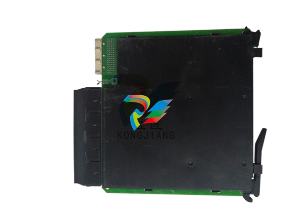
These are denoted by the letters P1 and P2. The board also has three additional connectors labeled JA through JC. These are BPIH subassembly plug connectors that mount into the faceplate connected to the circuit board. The board has a line of eighteen integrated circuits with a final integrated circuit near the board's center. TPC, TPX, TPB, and TPA are the designations for four sets of plated through-holes on the board. The front panels of the BICH board and BPIH board subassemblies contain high-density shielded connectors for these cables, ensuring shield continuity to the board rack chassis. On the BPIH board subassembly, control signals are buffered and interfaced with the FOSB board fiber-optic array through twisted pairs with differential signaling. Singular high-speed signals (such as VCO feedbacks) are terminated by a termination resistor at the receiving end. The RS-422 interface and distributor for all phase-related signals going to or coming from the BICH and FOSB boards is the BPIH board subassembly. BPIH is a subassembly on the Control Assembly Backplane that is commonly used as an auxiliary board. This board communicates with the BICH H bridge interface via three identical cables. Communication is done on a phase-by-phase basis (A/B/C). It is designed to fit into an Innovation series rack system. The Innovation Series is intended to fit into specific rack slots. Placing the board in the wrong slot may cause damage to the board or its components. Adhere to all replacement procedures outlined by the manufacturer in publications such as data sheets and manuals. If these publications are no longer available, this information is available in GE publication GEI-100417. Application Data There are no fuses, test points, LED indicators, or adjustable hardware on the BPIH board subassembly. There are three plug connectors (JA, JB, and JC) and two backplane connectors on the BPIH board subassembly (P1 and P2). Installation Procedure Place the board in the appropriate slot on the board rack. Because the Innovation Series boards/modules are built for certain rack spaces, placing the BPIH board subassembly into the incorrect slot can cause electronics damage. Begin seating the board by firmly pressing the top and bottom of the faceplate with your thumbs at the same time. Tighten the screws at the top and bottom of the faceplate to finish seating the board in the slot. To verify that the board is positioned squarely, tighten the screws evenly. Reconnect any electrical connections that were severed during step 3 of the board removal process. Snap the control cabinet door shut. Software In a ladder diagram format, application software is executed sequentially and represented in its dynamic state. Maintenance personnel have the ability to add, delete, or change analog loops, sequencing logic, tuning constants, and so on. To simplify editing, data points can be selected and dragged on the screen from one block to another. Other features include logic forcing, analog forcing, and frame rate trending. The documentation for application software is generated directly from the source code and printed on-site. This includes the primary elementary diagram, I/O assignments, tuning constant settings, and so on. The software maintenance tools are available in the HMI as well as as a separate software package for almost any Windows 95 or NT-based PC. System IONet Addressing The DHCP servers in the controllers assign IP addresses to IONet devices. The Host ID presented to the DHCP server is determined by the board type and serial number information stored on the terminal board's serial EEPROM. The I/O module can be replaced without having to update the toolbox or controller communication IDs because the Host ID is part of the terminal board. When replacing a terminal board, the user must associate the new Host ID with the configured device. To make this process easier, ToolboxST displays a list of unidentified devices that have requested IP addresses. When connecting an I/O pack to a main controller, IONet should only pass through five switches in series. Any configured IONet port on a controller or I/O module is constantly sending data, allowing the detection of faulty network cables, switches, or board components to occur immediately. When a fault occurs, the controller or I/O module generates a diagnostic alarm. IONets are class C networks. Each is its own network with its own set of subnet addresses. The IONet IP host addresses for the controllers are fixed. The ToolboxST assigns IP addresses to the I/O packs, and the controller automatically distributes the addresses to the I/O packs via a standard Dynamic Host Configuration Protocol (DHCP) server in the controllers. Output Processing The system outputs are the portions of calculated data that are transferred to external hardware interfaces and then to the various actuators that control the process. The output voting hardware votes on TMR outputs. Through simplex hardware, any system can output individual signals. The TMR system outputs are calculated independently by the three voting controllers. Each controller sends output to the I/O hardware associated with it (for example, the R controller sends output to the R I/O). A voting mechanism then combines the three independent outputs into a single output. Different signal types necessitate distinct methods for determining the voted value. Circuit Protection Fault current protection limits the current to what the system components can handle. Feedback from the branch circuit system Protection against ground faults in floating systems If possible, redundant applications Systems with multiple power applications run the risk of applying the incorrect power to a load or interconnecting power buses. To avoid this issue, the component employs specific connector conventions. Existing terminal board designs pose the greatest risk of incorrect connection. Regardless of whether the connection is AC or DC, these boards use a three-position Mate-N-Lok for power input. In addition, the existing boards have two parallel connectors for power daisy-chain wiring within a panel.BICH TO FOSB INTERFA
| User name | Member Level | Quantity | Specification | Purchase Date |
|---|


-
 Basler Electric ES Series Protection Relays
 -
 ABB Multifunction Protection and Switchbay Control Unit REF542plus
 -
 EMERSON AMS 2140 Machinery Health Analyzer
 -
 Hirschmann Industrial Ethernet Rail Switch RS20 Basic Family
 -
 GE Grid Solutions P40U Px40 USB Adaptor
 -
 ABB ontinuous Gas Analyzers AO2000 Series AO2040CU Ex Central Unit in Category 2G
 -
 ABB Advance Optima AO2000 Series Continuous gas analyzers Models AO2020. AO2040
 -
 Advance Optima Module Uras 14
 -
 SAACKE control optimization
 -
 SAACKE se@vis efficiency monitor
 -
 SAACKE se@vis pro
 -
 SAACKE se@vis eco
 -
 SAACKE se@vis compact
 -
 HIRSCHMANN Industrial ETHERNET Switch MICE MS20/MS30
 -
 HIRSCHMANN MICE Media modules
 -
 Kongsberg GL-10 Level Switch
 -
 B&R ACOPOSinverter P74 frequency converter
 -
 Beckhoff CX2020 | Basic CPU module (service phase)
 -
 Beckhoff CX1010 | Basic CPU module (service phase)
 -
 Beckhoff CX5120 | Embedded PC with Intel Atom® E3815
 -
 Beckhoff CP69xx-xxxx-0010 | Economy built-in Control Panel with DVI/USB Extended interface
 -
 Beckhoff CP29xx-0000 | Multi-touch built-in Control Panel with DVI/USB Extended interface
 -
 SAACKE Monoblock Rotary Cup Burner SKVJ-M
 -
 ABB Plantguard Fault Tolerant Technology Architecture and Software
 -
 OMRON H8PR-8/H8PR-8P H8PR-16/H8PR-16P H8PR-24/H8PR-24P Rotary Positioner
 -
 ABB PFSA107-Z42 DTU Stressometer Digital Transmission Unit
 -
 Nidec Mentor MP
 -
 IBA ibaNet-E
 -
 IBA FO Connection to Reflective Memory
 -
 IBA FO Connection to Siemens Systems
 -
 IBA Interface Cards For Fiber Optic Connections
 -
 IBA Field and Drive Buses
 -
 IBA ibaPADU-S Modular System
 -
 IBA ibaMAQS
 -
 STUCKE SYMAP®ARC
 -
 STUCKE SYMAP®R
 -
 STUCKE SYMAP®Compact
 -
 MOOG G123-825-001 BUFFER AMPLIFIER
 -
 Motorola MVME5100 Series VME Processor Modules
 -
 Motorola MVME162 Embedded Controller
 -
 HIMatrix Safety-Related Controller System Manual for the Modular Systems
 -
 Motorola MVME2400 Series VME Processor Module
 -
 Sieger System 57
 -
 KONGSBERG MRU product line continuation
 -
 Woodward easYgen-3100/3200 Genset Control for Multiple Unit Operation
 -
 Woodward MFR 300 Multifunction Relay / Measuring
 -
 ABB AX410, AX411, AX413, AX416, AX418, AX450, AX455 and AX456 Single and dual input analyzers for low level conductivity
 -
 ABB AX410, AX411, AX416, AX450 and AX455 Single and dual input analyzers
 -
 Woodward easYgen-1400 Technical Manual Genset Control
 -
 Woodward easYgen-400 Operation Manual Genset Control
 -
 Woodward High Output Digital Valve Positioner (DVP)DVP5000/DVP10000/DVP12000
 -
 Woodward High Output Digital Valve Positioner DVP5000 and DVP10000
 -
 Woodward TG611-13/-17 Overspeed Test Device Conversion Kit
 -
 Woodward MicroNet Safety Module (MSM)
 -
 Woodward 2301A Electronic Load Sharing and Speed Control 9905/9907 Series
 -
 Woodward-Service Bulletin 01671
 -
 UniOP eTOP40B 12.1” TFT color display
 -
 UniOP eTOP40 TFT Color display
 -
 UniOP eTOP33B 10.4” TFT color display
 -
 UniOP eTOP33C eTOP33-0050 Resistive touchscreen
 -
UniOP eTOP30. eTOP32 eTOP32-0050 Human-machine interface equipment
-
 UniOP eTOP20B and eTOP21B eTOP20B-0050
 -
 UniOP eTOP12 eTOP12-0050 Advanced human-machine interface equipment
 -
 UniOP eTOP11 eTOP11-0050 HMI
 -
 UniOP eTOP06C HMI
 -
 UniOP eTOP06 HMI
 -
 UniOP eTOP05EB eTOP05EB-DF45 HMI
 -
 UniOP eTOP05. eTOP05P Human-machine interface equipment
 -
 UniOP eTOP03 eTOP03-0046
 -
 UniOP eTOP507 507U2P1 eTOP Series 500 Human-Machine Interface
 -
 UniOP eTOP307
 -
 UniOP ETT-VGA Human-machine interface touch unit
 -
 UniOP ePAD32B, ePAD33B and ePAD33BT ePAD33B-0350
 -
 UniOP ePAD05 and ePAD06
 -
 UniOP CP02R-04 Human-machine interface
 -
 UniOP ERT-16 - Industrial PLC Workstation
 -
 UniOP ePAD03 and ePAD04
 -
 UNIOP EPALM10-DA71 state-of-the-art handheld HMI
 -
 Watlow SERIES CLS200 SPECIFICATION SHEET
 -
 Detailed Explanation of B&R Power Panel 300/400: The Core of Industrial Automation Control
 -
 YOKOGAWA Models ANB10S, ANB10D, ANR10S, ANR10D Node Units (for FIO)
 -
 Woodward ESDR 4 Current Differential Protection Relay
 -
 Woodward easYgen-3000 Genset Control for
 -
 Woodward CPC-II Current-to-Pressure Converter
 -
 Woodward 8290-189-EPG-installation-manual 8290-044
 -
 Woodward Product Change Notification 06946A
 -
 Woodward Product Change Notification 06912
 -
 Fisher™ 4660 High-Low Pressure Pilot
 -
 Flexible digital protection and control equipment SYMAP®
 -
 Woodward 723PLUS Digital Control
 -
 Woodward 505 Digital Controller For steam turbineses
 -
 Woodward 85018V2 505E Digital Governor for Extraction Steam Turbines
 -
Woodward 85018V1 Turbine Control Parameters
-
Woodward 26871 505 Enhanced Digital Control for Steam Turbines
-
 Woodward 03365 505E (Extraction / Admission)
 -
 KONGSBERG RMP420-Remote Multipurpose Input/Output
 -
 KONGSBERG RCU501 Remote Controller Unit
 -
 KONGSBERG RCU500 Remote Controller Unit
 -
 K-Gauge TOP KONGSBERG Tank Overfill Protection SystemFeatures
 -
 Kongsberg DPS112 DGNSS (DGPS/DGLONASS) sensor
 -
 Kongsberg d0000930-presafe-atex-report signed
 -
 HIMax TECHNICAL FACTS X Series
 -
 GE Multilin F650
 -
 GE MIF II - Legacy
 -
 GE PQM II Power QualIty Meter
 -
 Hydran 201Ti Mark IV Essential DGA monitoring for transformers
 -
 alstom AMS42/84 5B Amplifier SystemAmplifier Technology at its Best.
 -
 GE VMIVME-5576 Fiber-Optic Reflective Memory with Interrupts
 -
 GE Multilin 750/760 - Legacy Feeder Protection System
 -
 GE Fanuc Automation VMICPCI-7806 Specifications
 -
 VMIVME-7807 VME-7807RC* Intel® Pentium® M-Based VME SBC
 -
 GE Fanuc Automation VMIVME-7750 Specifications
 -
 FOXBORO Compact FBM240. Redundant with Readback, Discrete
 -
 FOXBORO FBM208/b, Redundant with Readback, 0 to 20 mA I/O Module
 -
 FOXBORO FBM201e Analog Input (0 to 20 mA) Interface Modules
 -
 Foxboro DCS FBM206 Pulse Input Module
 -
 FOXBORO FBM216 HART® Communication Redundant Input Interface Module
 -
 FOXBORO Z-Module Control Processor 270 (ZCP270)
 -
 FOXBORO Fieldbus Communications Module, FCM10Ef
 -
 FOXBORO Fieldbus Communications Module, FCM10E
 -
 Foxboro DCS Compact FBM241/c/d, Redundant, Discrete I/O Modules
 -
Foxboro FBM223 PROFIBUS-DP™ Communication Interface Module
-
 Foxboro DCS FBM204. 0 to 20 mAI/OModule
 -
Foxboro FBM239, Discrete 16DI/16DO Module
-
Foxboro FBM202 Thermocouple/mV Input Module
-
 Foxboro E69F Current-to-Pneumatic Signal Converter
 -
 EMERSON M-series Intrinsically Safe I/O
 -
 MVME6100 Series VMEbus Single-Board Computer


