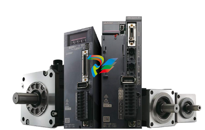
Module Overview
Chapter Objectives
Stepper Controller
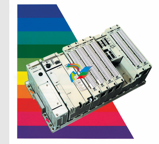
The Module overview will permit you to understand the basic functions of the Module and hardware requirements.
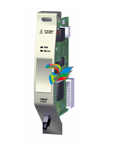
The Module, catalog number 1746–HSTP1, is an SLC 500 family compatible device. It can be used with any SLC 500 Processor.
The Module is configured through the SLC 500 backplane and requires no switch settings.
Motion can be programmed in either direction for over ±8,000,000 counts of absolute position.
An optional incremental encoder may be used to verify the position reached by the axis.

The Module does not automatically close a position loop in engineering units.
The feedback hardware can accept frequencies of up to 250 kHz for use as either loop back diagnostics or differential incremental encoder feedback devices.
The Module can be programmed for either incremental or absolute moves, depending on the application.
The Module supports two differential outputs, to suit the type of Stepper Translator used, which provide the following control commands:
• CW or non-directional pulse output
• CCW or direction signal output
Discrete inputs are provided for:
• External Interrupt
• Home Limit Switch
• Home Proximity Input
• CW Travel Limit Switch Input
• CCW Travel Limit Switch Input
• Pulse Train Enable/Disable Input
Differential inputs are provided for:
• Encoder Channel A and A NOT
• Encoder Channel B and B NOT
• Encoder Marker Channel

Command Mode Operation All stepper motor operations are performed in command mode.
This mode is entered by setting the mode flag (bit 15 in output word 0) to 0.
In command mode, the SLC Processor can issue commands and activate different operations or moves. The actions you can command are:
• Absolute Moves
• Relative Moves
• Hold Moves
• Resume Moves
• Immediate Stop Operations
• Homing Operations
• Jogging Operations
• Blend Moves
• Preset Operations
• Reset Errors
Diagnostic Mode
Use the configuration mode to select the diagnostic mode of operation. Once selected,
the diagnostic mode allows you to test your program and wiring by connecting the loop back wires at the
translator. The purpose of loop back diagnostics is to test the system wiring for electrical noise.
The number of pulses received at the feedback should equal the commanded number of pulses at the end of the move.
If they are not equal, the system may be experiencing problems due to electrical noise.
More Model Recommendations:
1756-OB16IS module Rockwell ControlLogix 16 digital output
1756-OB32 module Rockwell ControlLogix 32 digital output
1756-OB8 module Rockwell ControlLogix 8 digital output
1756-OB8EI module Rockwell ControlLogix 8 digital output
1756-OB8I module Rockwell ControlLogix 8 digital output
1756-OC8 module Rockwell ControlLogix 8 digital output
1756-OF4 module Rockwell ControlLogix 4 analog
1756-OF6CI module Rockwell ControlLogix 6 analog
1756-OF6VI module Rockwell ControlLogix 6 analog
1756-OF8 module Rockwell ControlLogix 8 analog
1756-OF8H module Rockwell ControlLogix 8 analog
1756-OG16 module Rockwell ControlLogix 16 digital output
1756-OH8I module Rockwell ControlLogix 8 digital output
1756-ON8 module Rockwell ControlLogix 8 digital output
1756-OV16E module Rockwell ControlLogix 16 digital output
1756-OV32E module Rockwell ControlLogix 32 digital output
1756-OW16I module Rockwell ControlLogix 16 digital output
1756-OX8I module Rockwell ControlLogix 8 digital output
1756-PA72 Module Rockwell ControlLogix AC Power Supply
1756-PA75 Module Rockwell ControlLogix AC Power Supply
1756-PA75R Module Rockwell ControlLogix AC Power Supply
1756-PAR2 Module Rockwell ControlLogix AC Power Supply
1756-PAXT Module Rockwell ControlLogix XT Power Supply
1756-PB72 Module Rockwell ControlLogix DC Power Supply
1756-PB75 Module Rockwell ControlLogix DC Power Supply
1756-PB75R Module Rockwell ControlLogix DC Power Supply
1756-PBR2 Module Rockwell ControlLogix Power Supply
1756-PBXT Module Rockwell ControlLogix XT Power Supply
1756-PC75 Module Rockwell ControlLogix DC Power Supply
1756-PH75 Module Rockwell ControlLogix DC Power Supply
1756-PSCA2 Module Rockwell ControlLogix Adapter
| User name | Member Level | Quantity | Specification | Purchase Date |
|---|


