
WOODWARD Load Sharing Module 0.5–4.5 Vdc Output 9907-252
Load Sharing Module
0.5–4.5 Vdc Output
9907-252
The Woodward Load Sharing Module is made for use with engines equipped with speed controls that
accept a 0–5 Vdc speed setting. The Load Sharing Module allows use of Woodward power generation
accessories and allows load sharing between engines equipped with speed controls that are not
manufactured by Woodward and engines controlled with Woodward electronic controls, or controls using
other Woodward load sharing modules.
Description
The Load Sharing Module provides isochronous and droop load-sharing capability for engines in
generator set applications. Additional equipment in the control system can include the Woodward SPM-A
Synchronizer, Import/Export Control, Automatic Generator Loading Control, and Automatic Power
Transfer and Loading Control.
Introduction
This section contains general installation instructions for the Load Sharing Module. Environmental
precautions and location considerations are included to determine the best location for the Load Sharing
Module. Additional information includes unpacking instructions, electrical connections, and an installation
check-out procedure.
Unpacking
Before handling the Load Sharing Module, read page ii, Electrostatic Discharge Awareness. Be careful
when unpacking the Load Sharing Module. Check the unit for signs of damage such as bent or dented
panels, scratches, and loose or broken parts. Notify the shipper of any damage.
Location Considerations
Consider these requirements when selecting the mounting location:
• Adequate ventilation for cooling
• Space for servicing and repair
• Protection from direct exposure to water or to a condensation-prone environment
• Protection from high-voltage or high-current devices, or devices which produce
electromagnetic interference
• Protection from excessive vibration
• An ambient operating temperature range of –40 to +70 °C (–40 to +158 °F)
Do not mount the Load Sharing Module on the engine.
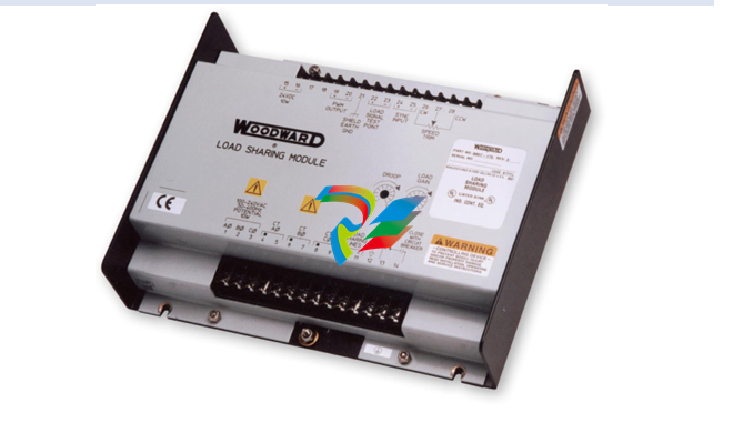
Figure 1-2 is an outline drawing of the Load Sharing Module. Install the unit as close as practical to the
electronic engine control, but not on the engine itself. It may be installed in any position.
To maintain compliance with CE and UKCA marking requirements, the European Union Low Voltage
Directive requires that the Load Sharing Module (LSM) be mounted in an IP43 enclosure as defined in
EN60529. Access to the Load Sharing Module must be restricted to qualified personnel.
General Wiring Requirements
The circled ground symbol identifies the Protective Earth Terminal. This terminal must be
connected directly to protective earth using a grounding conductor at least as large as those
used on terminals 1 through 9. The insulation of the grounding conductor must be of green and
yellow color.
This symbol identifies functional or EMC earth. This terminal is to be used for cable shield
connections only. It is not to be used as a protective earth terminal.
External wiring connections and shielding requirements for a typical installation are shown in the plant
wiring diagram, Figure 1-4. These wiring connections and shielding requirements are explained in more
detail in this chapter.
To maintain compliance with CE and UKCA marking requirements, the Low Voltage Directive requires
that the Load Sharing Module must only be connected to Class III equipment.
Wiring for the Load Sharing Module must be suitable for at least 90 °C (194 °F) and also be suitable for
the maximum installed operating temperature.
The Load Sharing Module must be permanently connected and employ fuses or circuit breakers in each
of the PT lines to limit current to the LSM PT inputs to no more than 5 A. In addition, a 2 A fast-acting fuse
or circuit breaker must be provided in the 24 Vdc power supply line.
All terminal block screws must be tightened to 0.56 to 0.79 N·m (5.0 to 7.0 lb-in).
To maintain compliance with CE and UKCA marking requirements, the EMC Directive requires that all
shields be connected to the terminals provided per the plant wiring diagram, Figure 1-4.
Power Requirements
The Load Sharing Module is powered from a 24 Vdc source. The 24 Vdc source must be a minimum of
18 Vdc and a maximum of 32 Vdc continuous. If a battery is used for operating power, an alternator or
other battery charging device is necessary to maintain a stable supply voltage.
Shielded Wiring
All shielded cable must be twisted conductors with either a foil or braided shield. Do not attempt to tin (put
solder on) the braided shield. All signal lines should be shielded to prevent picking up stray signals from
adjacent equipment. Connect the shields to the terminals indicated in the plant wiring diagram. Wire
exposed beyond the shield must be as short as possible.
The other end of the shields must be left open and insulated from any other conductor. Do not run
shielded signal wires with other wires carrying large currents. See Application Note 50532. EMI Control
for Electronic Governing Systems, for more information.
Where shielded cable is required, cut the cable to the desired length and prepare the cable as instructed
below and shown in Figure 2-1.
Introduction
This chapter describes the operation of the Load Sharing Module and its internal circuits. Figure 1-3 is a
block diagram of the circuits in the module.
The Load Sharing Module senses the power output of a generator and provides a 0.5–4.5 Vdc signal to
the speed control to adjust the power output of the engine-generator set to match the reference power
level. The Load Sharing Module can also produce a droop condition (instead of isochronous load
sharing), making it possible to connect the generator set in parallel with either a generator set which is
running isochronously, or with an infinite bus.
Power Supply
The internal power supply generates a regulated dc voltage for the operation of the circuits in the Load
Sharing Module. The power supply gets its power from the engine 24 Vdc power source. To prevent
damage to the unit that uses an alternator or battery charging device, make sure the charging device is
turned off before disconnecting or connecting the 24 Vdc supply to the unit.
Power Sensor
Generator load is measured by the power-sensor circuit of the Load Sharing Module. The power-sensor
circuit senses current amplitude and produces a load signal proportional to the current amplitude times
the power factor. The potential input comes from potential transformers (PTs) and the current input comes
from the current transformers (CTs). The circuit uses these two inputs to generate a load signal which is
then filtered and sent to the controller circuit. The load signal voltage of each generator set will be
proportional to the percentage of rated load on the generator set.
Ammeters and voltmeters may be driven with the same PT and CT wires.
Load Comparator Circuit
In the load comparator circuit, the load signal voltage is balanced with the other generator sets in the system via
the load sharing lines. The comparator circuit of each Load Sharing Module includes a load gain potentiometer to
adjust each generator set's load signal so that the load signal voltage of each is the same at full load. This
compensates for varying CT ratios or different generator set sizes. The load sharing voltage will be one-half the
measured voltage of the load signal test point.
Speed Trim Circuit
A speed-trim potentiometer can be added to the Load Sharing Module to permit remote adjustment of the
load or frequency of the generator. The speed trim is normally used for manual synchronization of a
generator set with an existing bus or to change the load demand when in droop mode.
Isochronous Load Sharing
Each comparator circuit compares the load signal voltage for its generator set to two times the voltage on
the load sharing lines and produces an error voltage proportional to the difference. This error voltage is
used to generate a pulse width modulated signal which is output to the speed control. This output biases
the speed loop of the speed control until the load signal voltage is equal to that of other generators on the
load sharing lines.
Droop Operation
In droop operation, a portion of the load signal voltage is fed to the controller circuit. This voltage is used
by the comparator circuit to reduce the control output by a percentage determined by the DROOP
potentiometer. The output is reduced, and the speed control reduces engine power output according to
the desired droop percentage.
When a generator set using the Load Sharing Module is paralleled in droop with other generator sets, the
common load signal on the paralleling lines is not used. The frequency of the generator set will therefore
vary with load, so it must be determined by a different means. In an isolated system with two or more
generator sets paralleled, if isochronous speed control is required, one of the generator sets must be
running in the isochronous (constant speed) mode. This generator set maintains the frequency of the
system. If a generator set is in droop and is paralleled with an infinite bus, the bus determines and
maintains the frequency. The DROOP percentage and the speed setting on the engine speed control
determine the amount of the load that is carried by the generator, when running in droop.
Auxiliary Equipment
The Woodward SPM-A synchronizer functions by biasing the output of the Load Sharing Module. All other
Woodward auxiliary generating control equipment functions by biasing the voltage on the load-sharing
lines.
0.5–4.5 Vdc Output
The Load Sharing Module output to the engine control is a 0.5 to 4.5 Vdc signal. The output nominally is
at 2.5 Vdc when the difference between the generator load and the signal on the load sharing lines is
zero.
The speed control should be set up in Variable Speed Governor mode to produce a ±10% variance in the
engine speed with a ±2.0 Vdc input, as shown in this example:
If 1800 rpm is equivalent to 60 Hz for a ±5.0% variance on the speed of the engine, the control would be
set up such that 0.5 Vdc output corresponds to 1710 rpm (VSG MIN
| User name | Member Level | Quantity | Specification | Purchase Date |
|---|


-
 Hirschmann Industrial Ethernet Rail Switch RS20 Basic Family
 -
 GE Grid Solutions P40U Px40 USB Adaptor
 -
 ABB ontinuous Gas Analyzers AO2000 Series AO2040CU Ex Central Unit in Category 2G
 -
 ABB Advance Optima AO2000 Series Continuous gas analyzers Models AO2020. AO2040
 -
 Advance Optima Module Uras 14
 -
 SAACKE control optimization
 -
 SAACKE se@vis efficiency monitor
 -
 SAACKE se@vis pro
 -
 SAACKE se@vis eco
 -
 SAACKE se@vis compact
 -
 HIRSCHMANN Industrial ETHERNET Switch MICE MS20/MS30
 -
 HIRSCHMANN MICE Media modules
 -
 Kongsberg GL-10 Level Switch
 -
 B&R ACOPOSinverter P74 frequency converter
 -
 Beckhoff CX2020 | Basic CPU module (service phase)
 -
 Beckhoff CX1010 | Basic CPU module (service phase)
 -
 Beckhoff CX5120 | Embedded PC with Intel Atom® E3815
 -
 Beckhoff CP69xx-xxxx-0010 | Economy built-in Control Panel with DVI/USB Extended interface
 -
 Beckhoff CP29xx-0000 | Multi-touch built-in Control Panel with DVI/USB Extended interface
 -
 SAACKE Monoblock Rotary Cup Burner SKVJ-M
 -
 ABB Plantguard Fault Tolerant Technology Architecture and Software
 -
 OMRON H8PR-8/H8PR-8P H8PR-16/H8PR-16P H8PR-24/H8PR-24P Rotary Positioner
 -
 ABB PFSA107-Z42 DTU Stressometer Digital Transmission Unit
 -
 Nidec Mentor MP
 -
 IBA ibaNet-E
 -
 IBA FO Connection to Reflective Memory
 -
 IBA FO Connection to Siemens Systems
 -
 IBA Interface Cards For Fiber Optic Connections
 -
 IBA Field and Drive Buses
 -
 IBA ibaPADU-S Modular System
 -
 IBA ibaMAQS
 -
 STUCKE SYMAP®ARC
 -
 STUCKE SYMAP®R
 -
 STUCKE SYMAP®Compact
 -
 MOOG G123-825-001 BUFFER AMPLIFIER
 -
 Motorola MVME5100 Series VME Processor Modules
 -
 Motorola MVME162 Embedded Controller
 -
 HIMatrix Safety-Related Controller System Manual for the Modular Systems
 -
 Motorola MVME2400 Series VME Processor Module
 -
 Sieger System 57
 -
 KONGSBERG MRU product line continuation
 -
 Woodward easYgen-3100/3200 Genset Control for Multiple Unit Operation
 -
 Woodward MFR 300 Multifunction Relay / Measuring
 -
 ABB AX410, AX411, AX413, AX416, AX418, AX450, AX455 and AX456 Single and dual input analyzers for low level conductivity
 -
 ABB AX410, AX411, AX416, AX450 and AX455 Single and dual input analyzers
 -
 Woodward easYgen-1400 Technical Manual Genset Control
 -
 Woodward easYgen-400 Operation Manual Genset Control
 -
 Woodward High Output Digital Valve Positioner (DVP)DVP5000/DVP10000/DVP12000
 -
 Woodward High Output Digital Valve Positioner DVP5000 and DVP10000
 -
 Woodward TG611-13/-17 Overspeed Test Device Conversion Kit
 -
 Woodward MicroNet Safety Module (MSM)
 -
 Woodward 2301A Electronic Load Sharing and Speed Control 9905/9907 Series
 -
 Woodward-Service Bulletin 01671
 -
 UniOP eTOP40B 12.1” TFT color display
 -
 UniOP eTOP40 TFT Color display
 -
 UniOP eTOP33B 10.4” TFT color display
 -
 UniOP eTOP33C eTOP33-0050 Resistive touchscreen
 -
UniOP eTOP30. eTOP32 eTOP32-0050 Human-machine interface equipment
-
 UniOP eTOP20B and eTOP21B eTOP20B-0050
 -
 UniOP eTOP12 eTOP12-0050 Advanced human-machine interface equipment
 -
 UniOP eTOP11 eTOP11-0050 HMI
 -
 UniOP eTOP06C HMI
 -
 UniOP eTOP06 HMI
 -
 UniOP eTOP05EB eTOP05EB-DF45 HMI
 -
 UniOP eTOP05. eTOP05P Human-machine interface equipment
 -
 UniOP eTOP03 eTOP03-0046
 -
 UniOP eTOP507 507U2P1 eTOP Series 500 Human-Machine Interface
 -
 UniOP eTOP307
 -
 UniOP ETT-VGA Human-machine interface touch unit
 -
 UniOP ePAD32B, ePAD33B and ePAD33BT ePAD33B-0350
 -
 UniOP ePAD05 and ePAD06
 -
 UniOP CP02R-04 Human-machine interface
 -
 UniOP ERT-16 - Industrial PLC Workstation
 -
 UniOP ePAD03 and ePAD04
 -
 UNIOP EPALM10-DA71 state-of-the-art handheld HMI
 -
 Watlow SERIES CLS200 SPECIFICATION SHEET
 -
 Detailed Explanation of B&R Power Panel 300/400: The Core of Industrial Automation Control
 -
 YOKOGAWA Models ANB10S, ANB10D, ANR10S, ANR10D Node Units (for FIO)
 -
 Woodward ESDR 4 Current Differential Protection Relay
 -
 Woodward easYgen-3000 Genset Control for
 -
 Woodward CPC-II Current-to-Pressure Converter
 -
 Woodward 8290-189-EPG-installation-manual 8290-044
 -
 Woodward Product Change Notification 06946A
 -
 Woodward Product Change Notification 06912
 -
 Fisher™ 4660 High-Low Pressure Pilot
 -
 Flexible digital protection and control equipment SYMAP®
 -
 Woodward 723PLUS Digital Control
 -
 Woodward 505 Digital Controller For steam turbineses
 -
 Woodward 85018V2 505E Digital Governor for Extraction Steam Turbines
 -
Woodward 85018V1 Turbine Control Parameters
-
Woodward 26871 505 Enhanced Digital Control for Steam Turbines
-
 Woodward 03365 505E (Extraction / Admission)
 -
 KONGSBERG RMP420-Remote Multipurpose Input/Output
 -
 KONGSBERG RCU501 Remote Controller Unit
 -
 KONGSBERG RCU500 Remote Controller Unit
 -
 K-Gauge TOP KONGSBERG Tank Overfill Protection SystemFeatures
 -
 Kongsberg DPS112 DGNSS (DGPS/DGLONASS) sensor
 -
 Kongsberg d0000930-presafe-atex-report signed
 -
 HIMax TECHNICAL FACTS X Series
 -
 GE Multilin F650
 -
 GE MIF II - Legacy
 -
 GE PQM II Power QualIty Meter
 -
 Hydran 201Ti Mark IV Essential DGA monitoring for transformers
 -
 alstom AMS42/84 5B Amplifier SystemAmplifier Technology at its Best.
 -
 GE VMIVME-5576 Fiber-Optic Reflective Memory with Interrupts
 -
 GE Multilin 750/760 - Legacy Feeder Protection System
 -
 GE Fanuc Automation VMICPCI-7806 Specifications
 -
 VMIVME-7807 VME-7807RC* Intel® Pentium® M-Based VME SBC
 -
 GE Fanuc Automation VMIVME-7750 Specifications
 -
 FOXBORO Compact FBM240. Redundant with Readback, Discrete
 -
 FOXBORO FBM208/b, Redundant with Readback, 0 to 20 mA I/O Module
 -
 FOXBORO FBM201e Analog Input (0 to 20 mA) Interface Modules
 -
 Foxboro DCS FBM206 Pulse Input Module
 -
 FOXBORO FBM216 HART® Communication Redundant Input Interface Module
 -
 FOXBORO Z-Module Control Processor 270 (ZCP270)
 -
 FOXBORO Fieldbus Communications Module, FCM10Ef
 -
 FOXBORO Fieldbus Communications Module, FCM10E
 -
 Foxboro DCS Compact FBM241/c/d, Redundant, Discrete I/O Modules
 -
Foxboro FBM223 PROFIBUS-DP™ Communication Interface Module
-
 Foxboro DCS FBM204. 0 to 20 mAI/OModule
 -
Foxboro FBM239, Discrete 16DI/16DO Module
-
Foxboro FBM202 Thermocouple/mV Input Module
-
 Foxboro E69F Current-to-Pneumatic Signal Converter
 -
 EMERSON M-series Intrinsically Safe I/O
 -
 MVME6100 Series VMEbus Single-Board Computer
 -
 Configuration for AMS 6500 Protection Monitors
 -
 Ovation™ Controller Model OCR1100 (5X00481G04/5X00226G04)
 -
 ABB UCU-22, UCU-23 andUCU-24control units


