
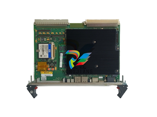
Part Number IS200IVFBG1A Manufacturer General Electric Country of Manufacture As Per GE Manufacturing Policy Series Mark VI/VIe Function Module Availability In StockIS200IVFBG1A is a Current Feedback Board developed by GE. It is a part of EX2100 excitation system. The Current Feedback Board, developed by GE, plays a critical role within the excitation system, specifically in applications involving a 3-level pulse-width modulated (PWM) inverter. Positioned within the load cabinet of the series, this board is integral to ensuring precise current feedback control, thereby enhancing the overall efficiency and performance of the system. INSTALLATION AND INTEGRATION Phase Leg Assembly: The Phase Leg Assembly forms the fundamental structure responsible for managing electrical phases within the 3-level pulse-width modulated (PWM) inverter system. Comprising semiconductor devices arranged strategically, it controls the switching operations that regulate current flow and voltage output. The Current Feedback Board plays a critical role in this assembly by continuously monitoring and precisely adjusting current levels, ensuring efficient power conversion and optimal performance of the inverter system. Back Base: Providing robust structural support and secure mounting points, the Back Base ensures the stability and proper alignment of various components within the load cabinet. It anchors the Current Feedback Board and other critical modules in place, safeguarding against vibrations and mechanical stresses that could affect operational reliability. This structural integrity is essential for maintaining consistent performance and facilitating ease of maintenance when necessary. Interface Module: The Interface Module acts as a pivotal intermediary within the excitation system, facilitating seamless communication and control interfaces between different system elements. It enables data exchange and synchronization between the Current Feedback Board, Phase Leg Assembly, and other subsystems. This coordination ensures cohesive operation and efficient management of system functions, enhancing overall reliability and responsiveness to operational demands. Capacitor Assembly Module: Central to energy storage and voltage stabilization, the Capacitor Assembly Module stores electrical energy and smoothens voltage levels within the inverter system. It absorbs transient currents and maintains stable voltage outputs, contributing to the system's reliability under varying load conditions. The Current Feedback Board collaborates closely with this module to regulate current feedback accurately, supporting consistent power delivery and minimizing fluctuations that could impact system performance. Blower Assembly: Critical for thermal management, the Blower Assembly provides essential cooling to maintain optimal operating temperatures for components housed within the load cabinet. By regulating heat dissipation, it prevents overheating and ensures the longevity and reliability of sensitive electronic parts, including the Current Feedback Board. Effective cooling is essential for sustaining performance accuracy and operational efficiency under demanding industrial environments. Cable Assemblies: Interconnecting various subsystems and components, Cable Assemblies establish essential electrical pathways for power distribution and signal transmission within the load cabinet. They facilitate seamless integration and communication between the Current Feedback Board, Phase Leg Assembly, Interface Module, and other critical system elements. This interconnectedness ensures coordinated operation and efficient energy management throughout the excitation system. AC Buswork: As the primary conduit for distributing AC power, the AC Buswork ensures efficient and reliable power supply to all components within the excitation system. It distributes electrical energy from the source to different modules, including the Current Feedback Board, ensuring consistent and stable operation. The board芒聙聶s integration with the AC Buswork is crucial for maintaining system integrity and optimizing performance, supporting continuous power generation processes without interruptions. SYSTEM SOFTWARE FEATURES The exciter system is designed with a high degree of flexibility and modularity, enabling it to be configured in various ways to suit different operational needs. This flexibility allows for a range of output currents and provides options for implementing different levels of redundancy within the system. Depending on the specific requirements of the application, operators can choose from configurations that include power from potential transformers connected to generator terminals, compound sources, or auxiliary sources via excitation transformers linked to auxiliary buses. These choices ensure that the exciter system can adapt seamlessly to different power distribution setups and operational scenarios. Redundancy is a key feature of the exciter system, offering options such as single or multiple bridges, warm backup bridges, and simplex or redundant controls. These redundancy options are critical for enhancing system reliability and minimizing downtime. Single bridges provide basic functionality, while multiple bridges allow for increased capacity and reliability by distributing load across multiple units. Warm backup bridges ensure rapid failover in case of primary bridge failure, maintaining continuity of operation without significant interruption. Similarly, simplex or redundant controls provide flexibility in how control signals are managed, ensuring that even in the event of control system failure, backup mechanisms can seamlessly take over to maintain operation. Feedback mechanisms within the exciter system are essential for monitoring and controlling performance. Key inputs include feedback from generator line current and stator output voltage, which are used to regulate and adjust the excitation levels. By monitoring these parameters closely, the exciter system can optimize its outputs of DC voltage and current to the exciter field. This controlled output is crucial for adjusting the magnetic field strength within the generator, thereby influencing voltage regulation and overall power quality.BD,PWM-3 CURRETN FEEDBACK
| User name | Member Level | Quantity | Specification | Purchase Date |
|---|


-
 ADLINK PCI/PCIe-7300A, cPCI-7300 32-CH 80 MB/s High-Speed Digital I/O Cards
 -
 ADLINK cPCI-7248/7249R 48-CH DIO & Timer/Counter Cards
 -
 ADLINK PCI-7230/7233/7234. LPCI/LPCIe/cPCI-7230 32-CH Isolated DIO Cards
 -
 ADLINK cPCI-6965 Series Value 6U CompactPCI® Intel® Core™2 Duo
 -
 ADLINK cPCI-6910 Series 6U CompactPCI® Dual-Core Intel® Xeon® Processor LV / ULV Universal Blade
 -
 ADLINK CPCI-6670 6U CompactPCI Low Power Pentium® III SBC
 -
 ADLINK cPCI-6625/6 Series 6U CompactPCI® PlusIO blade with Intel® Core™ i7/i3 Processor
 -
 ADLINK 3U CompactPCI CPU Modules
 -
 ADLINK CM-435 Extreme Rugged™ PC/104 Single Board Computer
 -
 ADLINK PCI-8254/8258 DSP-based 4/8-axis Advanced Motion Controllers
 -
 ADLINK NuPRO-E43 PICMG® 1.3 Full-Size LGA1151 with 6th/7th Generation Intel® Core™ i7/i5/i3
 -
 ADLINK DLAP-211-JNX/DLAP-211-JT2/ DLAP-211-Nano
 -
 Hirschmann RS30-1602O6O6SDAE compact OpenRail managed Ethernet switches
 -
Hirschmann RS30-0802O6O6SDAE Ethernet switch
-
 Hirschmann RS20-1600T1T1SDAE Management-type Ethernet switch
 -
 Hirschmann OCTOPUS 24M Limited Availability/Passive
 -
 Hirschmann MSP30-24040SCZ9MRHHE3A
 -
 Hirschmann MAR1040-4C4C4C4C9999SMMHRHHXX.X. Gigabit Ethernet Switch configurator
 -
 Hirschmann Industrial Ethernet Rail Switch SPIDER II, SPIDER II Giga, SPIDER II PoE
 -
 Hirschmann Industrial Ethernet Firewall EAGLE One
 -
 Hirschmann Industrial Security Router EAGLE20/30
 -
 Hirschmann Description and operating instructions RS2-xTX/xFX EEC
 -
 Basler Electric DECS-200 Digital Excitation Control System
 -
 Basler Electric GENERATOR PROTECTION SYSTEM BE1-GPS100
 -
 Jaquet FT3000 Speed measurement system
 -
 Hirschmann Industrial Ethernet Ruggedized Switch MACH1000 Family
 -
 Basler Electric BESTCOMSPlus®
 -
 ETEL AccurET MODULAR 300 EA-P2M-300-xxxxxA controller
 -
 Basler Electric ES Series Protection Relays
 -
 ABB Multifunction Protection and Switchbay Control Unit REF542plus
 -
 EMERSON AMS 2140 Machinery Health Analyzer
 -
 Hirschmann Industrial Ethernet Rail Switch RS20 Basic Family
 -
 GE Grid Solutions P40U Px40 USB Adaptor
 -
 ABB ontinuous Gas Analyzers AO2000 Series AO2040CU Ex Central Unit in Category 2G
 -
 ABB Advance Optima AO2000 Series Continuous gas analyzers Models AO2020. AO2040
 -
 Advance Optima Module Uras 14
 -
 SAACKE control optimization
 -
 SAACKE se@vis efficiency monitor
 -
 SAACKE se@vis pro
 -
 SAACKE se@vis eco
 -
 SAACKE se@vis compact
 -
 HIRSCHMANN Industrial ETHERNET Switch MICE MS20/MS30
 -
 HIRSCHMANN MICE Media modules
 -
 Kongsberg GL-10 Level Switch
 -
 B&R ACOPOSinverter P74 frequency converter
 -
 Beckhoff CX2020 | Basic CPU module (service phase)
 -
 Beckhoff CX1010 | Basic CPU module (service phase)
 -
 Beckhoff CX5120 | Embedded PC with Intel Atom® E3815
 -
 Beckhoff CP69xx-xxxx-0010 | Economy built-in Control Panel with DVI/USB Extended interface
 -
 Beckhoff CP29xx-0000 | Multi-touch built-in Control Panel with DVI/USB Extended interface
 -
 SAACKE Monoblock Rotary Cup Burner SKVJ-M
 -
 ABB Plantguard Fault Tolerant Technology Architecture and Software
 -
 OMRON H8PR-8/H8PR-8P H8PR-16/H8PR-16P H8PR-24/H8PR-24P Rotary Positioner
 -
 ABB PFSA107-Z42 DTU Stressometer Digital Transmission Unit
 -
 Nidec Mentor MP
 -
 IBA ibaNet-E
 -
 IBA FO Connection to Reflective Memory
 -
 IBA FO Connection to Siemens Systems
 -
 IBA Interface Cards For Fiber Optic Connections
 -
 IBA Field and Drive Buses
 -
 IBA ibaPADU-S Modular System
 -
 IBA ibaMAQS
 -
 STUCKE SYMAP®ARC
 -
 STUCKE SYMAP®R
 -
 STUCKE SYMAP®Compact
 -
 MOOG G123-825-001 BUFFER AMPLIFIER
 -
 Motorola MVME5100 Series VME Processor Modules
 -
 Motorola MVME162 Embedded Controller
 -
 HIMatrix Safety-Related Controller System Manual for the Modular Systems
 -
 Motorola MVME2400 Series VME Processor Module
 -
 Sieger System 57
 -
 KONGSBERG MRU product line continuation
 -
 Woodward easYgen-3100/3200 Genset Control for Multiple Unit Operation
 -
 Woodward MFR 300 Multifunction Relay / Measuring
 -
 ABB AX410, AX411, AX413, AX416, AX418, AX450, AX455 and AX456 Single and dual input analyzers for low level conductivity
 -
 ABB AX410, AX411, AX416, AX450 and AX455 Single and dual input analyzers
 -
 Woodward easYgen-1400 Technical Manual Genset Control
 -
 Woodward easYgen-400 Operation Manual Genset Control
 -
 Woodward High Output Digital Valve Positioner (DVP)DVP5000/DVP10000/DVP12000
 -
 Woodward High Output Digital Valve Positioner DVP5000 and DVP10000
 -
 Woodward TG611-13/-17 Overspeed Test Device Conversion Kit
 -
 Woodward MicroNet Safety Module (MSM)
 -
 Woodward 2301A Electronic Load Sharing and Speed Control 9905/9907 Series
 -
 Woodward-Service Bulletin 01671
 -
 UniOP eTOP40B 12.1” TFT color display
 -
 UniOP eTOP40 TFT Color display
 -
 UniOP eTOP33B 10.4” TFT color display
 -
 UniOP eTOP33C eTOP33-0050 Resistive touchscreen
 -
UniOP eTOP30. eTOP32 eTOP32-0050 Human-machine interface equipment
-
 UniOP eTOP20B and eTOP21B eTOP20B-0050
 -
 UniOP eTOP12 eTOP12-0050 Advanced human-machine interface equipment
 -
 UniOP eTOP11 eTOP11-0050 HMI
 -
 UniOP eTOP06C HMI
 -
 UniOP eTOP06 HMI
 -
 UniOP eTOP05EB eTOP05EB-DF45 HMI
 -
 UniOP eTOP05. eTOP05P Human-machine interface equipment
 -
 UniOP eTOP03 eTOP03-0046
 -
 UniOP eTOP507 507U2P1 eTOP Series 500 Human-Machine Interface
 -
 UniOP eTOP307
 -
 UniOP ETT-VGA Human-machine interface touch unit
 -
 UniOP ePAD32B, ePAD33B and ePAD33BT ePAD33B-0350
 -
 UniOP ePAD05 and ePAD06
 -
 UniOP CP02R-04 Human-machine interface
 -
 UniOP ERT-16 - Industrial PLC Workstation
 -
 UniOP ePAD03 and ePAD04
 -
 UNIOP EPALM10-DA71 state-of-the-art handheld HMI
 -
 Watlow SERIES CLS200 SPECIFICATION SHEET
 -
 Detailed Explanation of B&R Power Panel 300/400: The Core of Industrial Automation Control
 -
 YOKOGAWA Models ANB10S, ANB10D, ANR10S, ANR10D Node Units (for FIO)
 -
 Woodward ESDR 4 Current Differential Protection Relay
 -
 Woodward easYgen-3000 Genset Control for
 -
 Woodward CPC-II Current-to-Pressure Converter
 -
 Woodward 8290-189-EPG-installation-manual 8290-044
 -
 Woodward Product Change Notification 06946A
 -
 Woodward Product Change Notification 06912
 -
 Fisher™ 4660 High-Low Pressure Pilot
 -
 Flexible digital protection and control equipment SYMAP®
 -
 Woodward 723PLUS Digital Control
 -
 Woodward 505 Digital Controller For steam turbineses
 -
 Woodward 85018V2 505E Digital Governor for Extraction Steam Turbines
 -
Woodward 85018V1 Turbine Control Parameters
-
Woodward 26871 505 Enhanced Digital Control for Steam Turbines
-
 Woodward 03365 505E (Extraction / Admission)
 -
 KONGSBERG RMP420-Remote Multipurpose Input/Output
 -
 KONGSBERG RCU501 Remote Controller Unit
 -
 KONGSBERG RCU500 Remote Controller Unit
 -
 K-Gauge TOP KONGSBERG Tank Overfill Protection SystemFeatures
 -
 Kongsberg DPS112 DGNSS (DGPS/DGLONASS) sensor


