DCS; Industrial control system
NameDescriptionContent
Argument
Current Location:
PRODUCT SHOW
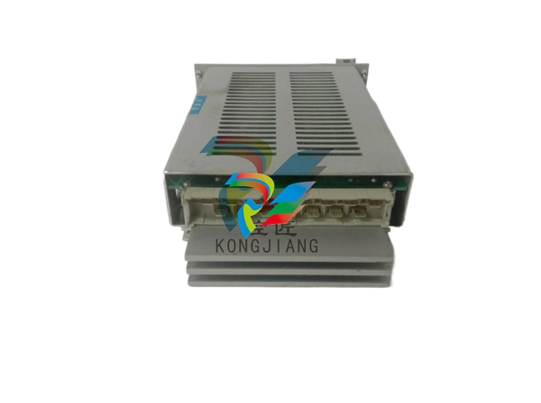
IS200RAPAG1A
❤ Add to collection

IS200RAPAG1A

IS200RAPAG1A
10055.00
¥4548.00
¥4548.00
¥4548.00
Weight:0.000KG
Description
IS200RAPAG1A

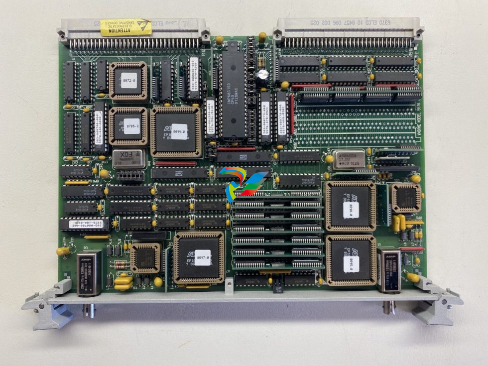
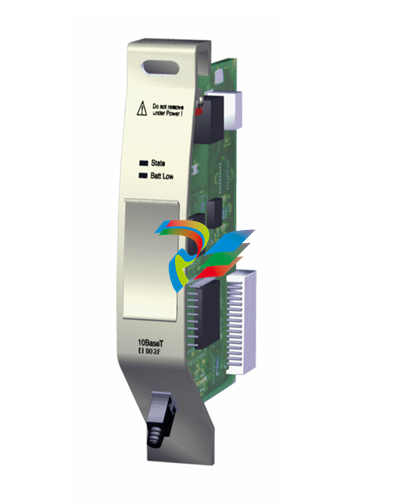
Part Number IS200RAPAG1A Manufacturer General Electric Country of Manufacture As Per GE Manufacturing Policy Series Mark VI/VIe Function Module Availability In StockIS200RAPAG1A is a Rack Power Supply Board developed by General Electric. It is a part of Mark VI control system. The board is equipped with essential components to ensure seamless operation within the control system. It features a 1 amp, 250 V fuse, a 24 Vdc isolated power supply, a serial 1024-bit memory device, and a parallel-style bus host processor. These components collectively facilitate the reliable distribution of power and data throughout the system. OPERATION DC Control Voltage Provision: The primary function of the board is to supply the necessary DC control voltages required by other boards housed within the Innovation Series board rack. The P1 connector interface, located on the board, establishes a connection with the system's backplane, enabling the distribution of control voltages to various components within the rack. Interface with Backplane: The P1 connector serves as the interface point through which the board communicates with the backplane of the Innovation Series rack. This interface ensures seamless integration and coordination with other boards, facilitating the exchange of control signals and voltage distribution across the system. Control Over System Functions: In addition to voltage provision, the board assumes control over critical system functions such as Power ON and Master RESET. By managing these functions, the board ensures the smooth operation and integrity of the overall system, initiating startup sequences and system resets as required. System Integrity Assurance: The board plays a crucial role in maintaining system integrity by overseeing essential operational aspects. It monitors power supply statuses, initiates necessary resets, and ensures that all connected components receive the required control voltages for optimal performance. Coordination with Other Boards: As part of a larger control system, the board coordinates closely with other boards within the Innovation Series rack. It collaborates with neighboring boards to synchronize system activities, exchange data, and maintain operational consistency across the entire system. Continuous Monitoring and Adjustment: Throughout operation, the board continuously monitors system parameters and adjusts control voltages as needed to meet dynamic operational demands. This adaptive control mechanism ensures reliable performance and system stability under varying conditions. INSTALLATION Locate P1 Backplane Connector: Identify the P1 backplane connector within the Innovation Series board rack. This connector serves as the interface for connecting the board to the rack's backplane. Align Connector Rows: The P1 connector consists of three rows, each featuring 32 pins. Ensure proper alignment of the board's connector with the corresponding rows on the P1 connector to facilitate secure and reliable connectivity. Connect Board: Carefully insert the board into the P1 backplane connector, ensuring that the pins on the board's connector align correctly with the corresponding pins on the connector rows. Apply gentle pressure to firmly seat the board in place, ensuring a stable connection. Verify Installation: After connecting the board, visually inspect the connection to confirm that it is secure and properly aligned. Verify that all pins are fully engaged and there are no gaps between the board and the backplane connector. Check Diagnostic Elements: Take note of the additional diagnostic elements provided on the board. These include two LED indicators and four test points, which offer valuable diagnostic information for system maintenance and troubleshooting purposes. Ensure Proper Functionality: Power on the system and verify that the board is functioning as expected. Monitor the LED indicators for abnormal behavior and use the test points to perform diagnostic tests. Secure the Installation: Once the board is successfully installed and verified, ensure that it is securely fastened within the rack to prevent any movement or disconnection during operation. FRONT PANEL FEATURES Reset Switch: An accessible reset switch is provided on the front panel, allowing users to initiate system resets with ease when necessary. Test Points (TP): Four TP (Test Point) connections are available on the front panel, facilitating diagnostic testing and troubleshooting procedures. These test points enable technicians to measure and monitor key parameters of the board's operation for maintenance purposes. LED Indicators: Two LED indicators, labeled MPOK and IPOK, are prominently featured on the front panel. The MPOK indicator provides visual feedback on the status of the board's main power, while the IPOK indicator indicates the status of the board's input power. These LED indicators offer at-a-glance monitoring of essential system parameters, enhancing overall visibility and awareness. Secure Attachment: The front panel is securely attached to the circuit board via two screw connections. This robust attachment mechanism ensures durability and stability during operation, minimizing the risk of detachment or damage. User-Friendly Design: The front panel's layout and design prioritize user-friendliness, providing convenient access to essential features and diagnostic elements. Clear labeling and intuitive placement of controls and indicators enhance usability and streamline troubleshooting processes. Durability and Stability: Built to withstand demanding industrial environments, the front panel's construction and attachment mechanism are optimized for durability and stability. This ensures reliable performance even in challenging operating conditions, contributing to the overall longevity of the board. PROTECTION AND COMPONENTS Critical to its functionality, the board incorporates a 1 amp, 250 V fuse, safeguarding the 24 Vdc isolated power supply from potential electrical faults. Integrated circuits, including a serial 1024-bit memory device, ensure efficient data management and processing. The board also features transistors, heat sinks, capacitors (including high-voltage capacitors), resistors, and an inductor coil, collectively contributing to its robust design and performance.BD,RACK POWER SUPPLY

  • Sixnet® SL-8ES-1 Unmanaged 8-port Industrial Ethernet Switch
  • ABB NE810 3BSE080207R1 Network switch
  • N-Tron® 1008TX Unmanaged 8-port Gigabit Industrial Ethernet Switch
  • N-Tron® 106FX2-SC-MDR Unmanaged 6-port Industrial Ethernet Switch
  • Sixnet® SLX-9ES-3SC Unmanaged 9-port Industrial Ethernet Switch
  • N-Tron® 106FXE2-SC-80-MDR Unmanaged 6-port Industrial Ethernet Switch
  • Sixnet® SLX-5ES-3SC Unmanaged 5-port Industrial Ethernet Switch
  • Emerson Smart Wireless Gateway 1552WU
  • Emerson wireless control bridge
  • Emerson field data is wirelessly transmitted back
  • Emerson Wireless Remote Video Surveillance
  • Emerson DeltaV™ S series 4-port FF fieldbus I/O
  • Emerson DeltaV™ S series DeviceNet interface cards
  • Emerson DeltaV™ S series H1 I/O card with integrated power supply
  • Emerson DeltaV™ S series centralized connection solutions
  • Emerson DeltaV™ S series Profibus DP interface card
  • Emerson DeltaV™ S series serial interface
  • Emerson DeltaV™ S series SX controller
  • Emerson DeltaV™ Recipe Exchange
  • Emerson DeltaV™ Mobile
  • Emerson DeltaV™ M Series enhanced DC-to-DC power supply
  • Emerson DeltaV™ Virtual S Series and M Series controller simulation
  • Emerson DeltaV™ PK Flex controller
  • Emerson DeltaV Flex system
  • Emerson DeltaV™ M series Profibus DP Series 2 Plus interface card
  • Emerson DeltaV CTO DCS cabinet
  • Ntron Senz-TX oxygen sensor transmitter
  • ntron Compact SIL2 Capable Oxygen Analyzer – Ntron SIL-O2
  • Oxygen Analyzer – Ntron Microx
  • Medical Gas Analyzer – Ntron MoGas
  • Intrinsically Safe Compact Oxygen Transmitter – Minox-i
  • Ntron Microx-OL
  • Portable Oxygen and Moisture Analyzer – Ntron AM Trace
  • In-Line Process Oxygen Analyzer – Ntron OxyExtract
  • Ambient Oxygen Analyzer – Ntron Gasenz
  • Portable Oxygen Analyzer – Ntron Yellow Box
  • Industrial Oxygen Analyzers – GPR-1900 and GPR-2900
  • Oxygen Monitors – AII GPR-1500 GB/2500 GB
  • Thermo-Paramagnetic Oxygen Analyzer – Michell XTP501
  • Paramagnetic Oxygen Analyzer – Michell XPM601
  • N-Tron® NT24K-12GX4-SC-80 Industrial Ethernet Switch
  • N-Tron® NT24K-14FXE6-SC-80 Managed 14-Port Gigabit Industrial Ethernet Switch
  • N-Tron® 7012FXE2-SC-40 Managed 12-port Industrial Ethernet Switch
  • N-Tron® NT24K-11GX3-SC-PT Gigabit Industrial Ethernet Switch
  • N-Tron® NT24K-14FXE6-SC-15 Managed 14-Port Gigabit Industrial Ethernet Switch
  • N-Tron® 7018FXE2-SC-15 Managed 18-port Industrial Ethernet Switch
  • N-Tron® NT24k 24-Port Rackmount Gigabit Managed Industrial Ethernet Switch
  • N -Tron® 710FXE2-ST-80 Managed 10-port Industrial Ethernet Switch
  • N-Tron® NT24k 24-Port, Dual Redundant VDC Power Input
  • N -Tron® 712FXE4-SC-15-HV Industrial Ethernet Switch
  • N -Tron® 712FXE4-ST-15-HV Industrial Ethernet Switch
  • N-Tron® NT24K-10FX2-SC Industrial Ethernet Switch
  • N -Tron® 709FXE-SC-40 Managed 9-port Industrial Ethernet Switch
  • N-Tron® NT24K-12SFP-DM4 Gigabit Industrial Ethernet Switch
  • N-Tron® NT24k 16-Port, Single Redundant VDC Power Input
  • GE Multilin C30 Controller System
  • GE Multilin C650 Bay Control & Monitoring System
  • GE Reason MU320E
  • GE Reason MU360
  • GE MiCOM C264 Bay Controller
  • GE Multilin C60/C95 C60 Breaker Monitoring and Control
  • GE Multilin D.20 I/O Modules
  • GE Multilin D20E Advanced Substation I/O Modules
  • GE Multilin™ G500 Advanced Substation Gateway
  • GE Multilin™ G100 Advanced Substation Gateway
  • GE iSTAT i4Mx Standard multifunction transducer
  • iSTAT M365 Power Quality Metering with Extensive Logging and Communications
  • GE iSTAT M2x3 High Performance Measurement Centre
  • GE iSTAT M2x2 Standard Measurement Centre family
  • iSTAT i400 Mean Sensing Transducers and i4XS Communications Interface
  • GE iSTAT i500 High Performance Multifunction Transducer
  • GE MVTP Buswire Supervision Relay
  • GE MFAC High Impedance Bus Differential Relay
  • GE MCAG High Impedance Bus Differential Relay
  • GE P40 Agile P14N, P14D, P94V P40 Agile Feeder Management
  • GE MiCOM Agile P140 Series
  • GE MiCOM Agile P746 Centralized Busbar Differential Relay
  • GE MiCOM Agile P747 Centralized Busbar Differential Relay
  • GE Multilin B90 Low Impedance Bus Protection System
  • GE MiCOM Agile P74x Series
  • GE Multilin B30 Multiple Sections Low Impedance Busbar Protection
  • GE Dolin G60 generator protection system
  • ABBPCS 8000 AC Excitation AC Excitation for hydro pump energy storage plants
  • ABBCompact Product Suite Panel 800 Version 6 PP877 Hardware and Installation
  • ABBIndustrialIT Panel 800 - PP865 Version 5.1 Hardware and Installation
  • ABBSYSTEM DRIVES MEGADRIVE-LCI water-cooled User manual
  • ABBAdvant® Controller 450 The proven process controller
  • ABBAdvant® Master S100 I/O system
  • SYNCHROTACT® 5 Operating Instructions SYN 5201 SYN 5202
  • ABB EXCITATION SYSTEMS AND SYNCHRONIZING EQUIPMENT SYNCHROTACT® 5 Documentation Access
  • ABBAdvant® Master S100 I/O system
  • ABBCI853 Compact Product Suite hardware selector
  • ABBAC 800M and Communication interfaces Compact Product Suite Outline of all modules
  • ABBAC 800M Controller Hardware Product Guide
  • ABBAC 800M PROFIBUS DP Configuration
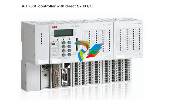
  • ABBCompact control system replaces PLCs Comfortable, more efficient integration of package units using AC 700F
  • ABBDistributed busbar protection REB500 including line and transformer protection Product Guide
  • ABB Procontic Progamming System 907 PC 331 Programming and Test Software
  • ABBDCS800 Quick guide DCS800 Drives (20 A to 5200 A)
  • ABBDCS Thyristor Power Converters for DC Drive Systems 25 to 5150 A Operating Instructions DCS 600 MultiDrive
  • ABBDrivetrain vibration damping with MEGADRIVE-LCI Improve reliability, extend lifetime and enhance performance
  • ABBMEGADRIVE-LCI water-cooled User manual
  • ABBDCS800 Hardware Manual DCS800 Drives (20 to 5200 A)
  • ABBDCS800 Quick guide DCS800 Drives (20 A to 5200 A)
  • ABBDCS Thyristor Power Converters for DC Drive Systems 25 to 5150 A Operating Instructions DCS 600 MultiDrive
  • ABBAdvant® OCS Open Control SystemAdvant Controller 110
  • ABBAdvant® OCS Open Control SystemAdvant Controller 210
  • ABBAdvant Fieldbus 100 User Manual
  • ABBAdvant® OCS Open Control SystemAdvant Controller 250
  • ABBAdvant Controller 160
  • ABBIndustrial Networks Connecting Controllers via OPC
  • ABBAdvant® OCSOpen Control SystemAdvant Controller 70
  • ABBAdvant Controller 31 40 & 50 Series
  • ABB Procontic CS 31 Intelligent decentralized automation system
  • ABBAdvant Controller 31 Intelligent Decentralized Automation System
  • ABBHardware Manual ACV 700 Frequency Converters
  • ABBGet more done better with Advant Controller 400 series
  • ABBElectro-Pneumatic Positioner TZIDC
  • ABBCase note ABB MNS iS The integrated solution for the WAGP project
  • ABBCondition MonitoringMService V7.7 - User Manua MService V7.7 - User Manua [Document Type] ABB Ability™ Condition Monitoring for electrical systems - CMES User Manual MService Condition Monitoring V7.7 User Manual
  • ABBMNS® Digital ABB Ability™ Condition Monitoring for electrical systems - CMES User Management – Quick guide ABB Ability™ Condition Monitoring for electrical systems – CMES User Management Quick Guide
  • ABB MEASUREMENT & ANALY TICS | DATA SHEET 266DSH Differential pressure transmitters
  • General Specifications FCN Autonomous Controller Hardware (FCN-500)
  • Unicom-JETNETJetNet 4510 Industrial 10-port Management Fast Ethernet Switch
  • TCC-80Port-powered RS-232 to RS-422/485 converter
  • Temaline Wiegand ModuleDigital Wiegand Multi I/O Management Device
  • ABBAC 800M Controller Hardware
  • MD00R-02/04 - Industrial PLC Workstation