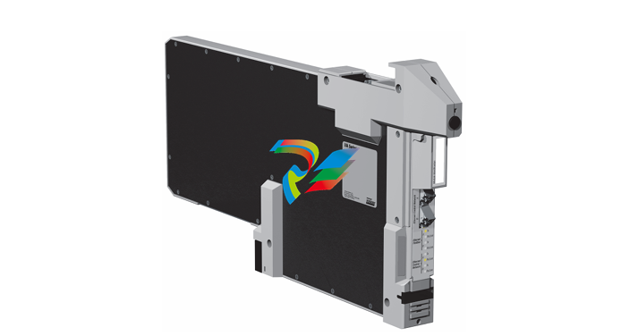
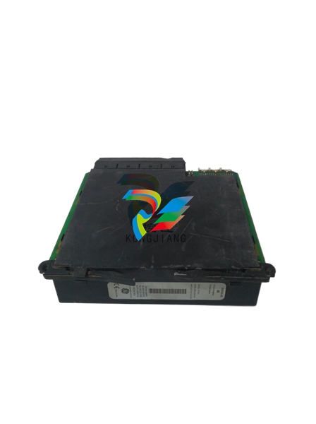
Part Number IS200BICMH1A Manufacturer General Electric Country of Manufacture As Per GE Manufacturing Policy Series Mark VI/VIe Function Module Availability In StockIS200BICMH1A is an IGBT Gate Driver Board developed by GE. It is designed under the Drive Control system. On the faceplate of the printed circuit board, there is an LED indicator light at the top, with white text to the right that reads, IMOK. There are two long, thin, rectangular holes beneath that. This top hole has several labels down the right side that read: IA, IB, IC, VAB, VBC, VDCP, VMID, VDCN, ACOM. The bottom hole also has several labels down the right side that read: DA1, DA2, DA3, DA4, TRG1, TRG2, ACOM. There is white text at the bottom of the faceplate that reads, install in slot 5 only. As the name implies, the circuit is designed to be installed only in slot 5 of a GE rack assembly. Features The faceplate provides access to user TP test points. These are located directly behind the panel's narrow openings and correspond to corresponding labels located to the right of the opening. Next to the first opening, these labels are 1A, 1B, 1C, VAB, VBC, VDCP, VMG, VDCN, and ACOM, and next to the second opening, they are DA1 through DA4, TRG1, TRG2, and ACOM. TP1 through TP9 are aligned behind the first opening, while TP14 through TP16 are aligned behind the second. Many more test points can be found throughout the board. Two backplane connectors (P1/P2) and four vertical male pin connectors are included on the board. Three of these are stacked on top of each other and labeled POD1, POD2, and POD3. The final connector can be found directly behind the front faceplate. A ten-pin connector is used. There are over 150 capacitors, 300 resistors, and 100 integrated circuits. A single metal oxide varistor and five resistor network arrays were used to construct the board. The board carries the code 6BA02 just above the board number. The board is capable of operating at high voltage levels, making it suitable for use in high-power applications. It has built-in protection features to ensure safe and reliable operation, such as protection against overvoltage, overcurrent, and short circuit conditions. The board has a variety of input and output connections, including digital inputs, digital outputs, and analog inputs, allowing for integration with a wide range of control systems and components. Product Attributes Purpose: Designed to control the switching of IGBTs in power conversion systems. Voltage: The board is capable of operating at high voltage levels, making it suitable for use in high-power applications. Control: Provides fast and accurate control of IGBT switching, ensuring efficient and reliable operation of the power conversion system. Protection: The board has built-in protection features, such as overvoltage protection, overcurrent protection, and short circuit protection, to ensure safe and reliable operation. Connectivity: It has a variety of input and output connections, including digital inputs, digital outputs, and analog inputs, for integration with a wide range of control systems and components. Compatibility: The board is designed to be compatible with a variety of control systems and platforms, making it a versatile option for system integrators and end-users. Performance: Engineered to provide high-performance operation, with fast switching speeds and high accuracy, to meet the demands of power conversion applications. BICM Card Clock Fail The BICM card clock fail trip fault occurs when the BICM's FPGA logic is unable to detect the presence of either of its clock signals. One of the clocks it seeks is generated by a crystal on the BICM itself, while the other is transmitted from DSPX via the rack backplane. BICM Card Temp Low When the sensor on the BICM measures a temperature of 20C or less, the BICM card temp low trip fault occurs. The variable being monitored to generate this fault is BIC ambient temperature. BIC Watchdog When the BICM no longer sees a watchdog toggle bit from the DSPX, the BIC Watchdog trip fault occurs. BICM monitors a toggle bit being manipulated by DSPX while the drive is running. If DSPX fails to toggle the BICM bit within a predetermined time interval, the BICM declares a fault and disables the bridge. This indicates that the processor is unable to communicate with the bridge interface card reliably. To clear the BIC Watchdog, a hard reset is required.IGBT GATE DRIVER
| User name | Member Level | Quantity | Specification | Purchase Date |
|---|


