
Part Number IS200IGDMH1B Manufacturer General Electric Country of Manufacture As Per GE Manufacturing Policy Series Mark VI/VIe Function Module Availability In StockIS200IGDMH1B is an IGBT gate driver board developed by GE. It is a part of EX2100 excitation system. The EX2100 is compatible with both static and rotating exciters such as brushless and Alterrex. The architecture communicates via Ethernet LAN (Unit Data Highway) with other GE equipment such as the GE Control System Toolbox (toolbox) for configuration, the turbine control, the LCI Static Starter, and the HMI (operator interface). The exciter receives power from either a power potential transformer connected to the generator terminals or an excitation transformer connected to an auxiliary bus.
The primary feedbacks to the exciter are generator line current and stator output voltage, and the controlled output to the exciter field is dc voltage and current. IS200IGDMH1B Features It is a specialized board developed by GE with specific features and functions. Notably, this board does not have a traditional faceplate but is attached to a sub-strata made of a moldable material, which provides stability and support. The board is equipped with two vertical male two-pin connectors, labeled J1 and J2, as well as a single pin connector labeled J3. These connectors serve as connection points for various external components and wiring. In addition to the connectors, the board includes two plastic connectors and several terminal connections, allowing for secure and reliable connections within the system. An auxiliary board is soldered to the primary board, providing additional functionality and support. This auxiliary board carries several additional components, including capacitors, which contribute to the overall operation and performance of the system. The stacking of the auxiliary board with a heat sink component ensures effective heat dissipation, maintaining optimal operating temperatures and extending the lifespan of the board and its components. It is crucial to note that in the event of an IGBT (Insulated-Gate Bipolar Transistor) module failure, the board is often damaged as well and necessitates replacement. This highlights the interconnected nature of the board and its dependency on the IGBT module for proper functioning. When a failure occurs, it is necessary to replace the entire IGDM board to ensure the continued reliability and operation of the system.
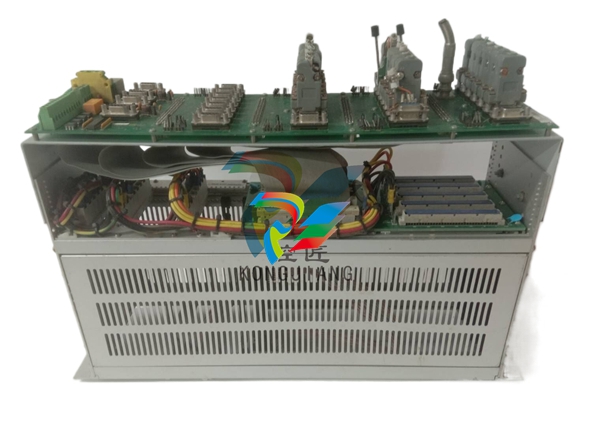
The board features a unique design with no traditional faceplate, being attached to a sub-strata for stability. It incorporates vertical male connectors, plastic connectors, and terminal connections to facilitate external connections. The auxiliary board soldered to the primary board enhances functionality and carries additional components such as capacitors. The presence of a heat sink component ensures efficient heat dissipation. It is important to replace the entire board in the event of an IGBT module failure to ensure proper system operation. Operator Interface Mark VI system features a PC-based HMI (operator interface) for comprehensive system data access. Provides real-time access to events, alarms, and time tags from a centralized location. IGBT Gate Driver Board Functions as an IGBT Gate Driver board. IGBTs are key components for power control in electronic systems. Components Houses over 10 integrated circuits, transformers, resistors, capacitors, diodes, and more. Incorporates various connectors, including J1, J2, and J3. Auxiliary board soldered onto the primary board, enhancing functionality. Thermal Considerations Auxiliary board and heat sink component work together to manage heat. Reflects meticulous design for efficient thermal management. Software Overview The software utilized in the drive application program of the system is structured around functional software modules, acting as building blocks that collaborate to fulfill system requirements and ensure smooth operation. The EEPROM (Electrically Erasable Programmable Read-Only Memory) plays a significant role in storing block definitions and configuration parameters essential for the drive's operation. These parameters can be customized to suit specific system requirements and allow for efficient control and performance optimization. On the other hand, variables and dynamic data are stored in RAM (Random Access Memory), providing the flexibility to adapt to real-time changes in the system. Tune-up and diagnostic software components are integrated into the system, working transparently to the user. These components handle tasks such as optimizing drive performance and diagnosing any issues that may arise. By seamlessly integrating these software functionalities, the system can ensure optimal performance without burdening the user with complex manual adjustments or diagnostics. To facilitate operator control and interaction with the system, a door-mounted interface unit is provided. This interface unit offers a user-friendly menu-driven interface, allowing operators to navigate through various selections and perform control operations effortlessly. The menu-driven system enables operators to access and modify system settings, initiate specific functions, and monitor the drive's performance. The drive continuously monitors its performance, ensuring smooth operation and fault detection. The results of this monitoring process are displayed to the operator through animated meters, icons, and digital values on the Digital Display Interface (DDI). This real-time feedback provides operators with a clear understanding of the drive's performance and operational status, allowing for timely response and intervention when necessary. In addition to performance monitoring, the software also enables the operator to examine and reset any faults that may occur during operation. Through additional menus, operators can access detailed fault information, examine the root cause of the fault, and take appropriate corrective actions. The ability to reset faults through the software interface streamlines the troubleshooting process and helps to ensure uninterrupted operation of the system. System Hardware Overview The EX2100 hardware is housed in the following cabinets: Control Cabinet: Responsible for housing the control, communication, and input/output (I/O) boards. These boards are vital for the overall operation and control of the excitation system. The control board manages and regulates various functions, including monitoring system performance, executing control algorithms, and communicating with other system components. The communication board enables seamless communication between the excitation system and other control systems or interfaces. The I/O boards facilitate the interaction between the excitation system and external devices, allowing for the exchange of signals and data. Auxiliary Cabinet: Dedicated to field flashing and protection circuits, including de-excitation and shaft voltage suppression circuits. These circuits play crucial roles in ensuring safe and reliable operation of the excitation system. The field flashing circuit is responsible for providing the initial excitation current to the generator field winding during startup. Protection circuits, such as de-excitation and shaft voltage suppression, protect the generator and excitation system from potential damage due to abnormal conditions or voltage spikes. Power Conversion Cabinet: Houses the silicon-controlled rectifier (SCR) cells, cooling fans, DC contactors, and an AC disconnect. The SCR cells are key components responsible for converting AC power to controlled DC power. The cooling fans are integrated into the cabinet to dissipate heat generated during operation, ensuring optimal temperature levels and preventing overheating. The DC contactors facilitate the switching and control of the DC power output, allowing for proper regulation and distribution. The AC disconnect provides a means to safely disconnect the AC power supply to the system when necessary for maintenance or emergency purposes. De-Excitation Therefore the SCR conducts and dissipates the stored energy of the generator field through the field discharge device. Feedback from either conduction sensor verifies that the discharge circuit has operated successfully. If both independent firing control circuits fail to fire, the SCR is fired by the anode firing circuit when the anode to cathode voltage has exceeded the selected level. For large exciters, it is possible to connect multiple de-excitation modules together with one board configured to be the Master and the other boards configured to be Slaves. As a result, the SCR conducts and dissipates the generator field's stored energy via the field discharge device. Feedback from either conduction sensor confirms that the discharge circuit worked properly. If both independent firing control circuits fail to fire, the anode firing circuit fires the SCR when the anode to cathode voltage exceeds the selected level. Multiple de-excitation modules can be connected together for large exciters, with one board configured as the Master and the other boards configured as Slaves. Control Module The control module in the EX2100 system is designed as a VME-style rack, featuring multiple boards that are cable connected to the I/O terminal boards. This rack serves as the backbone of the control system, housing the essential components required for managing the motor and its associated processes. The control module's architecture provides a flexible and modular setup, allowing for efficient control and communication between various elements of the system. The VME-style rack is divided into three distinct and independently powered sections, each dedicated to a specific controller within the system. These controllers are referred to as M1, M2, and C controllers:IGBT GATE DRIVER
| User name | Member Level | Quantity | Specification | Purchase Date |
|---|


-
 Basler Electric ES Series Protection Relays
 -
 ABB Multifunction Protection and Switchbay Control Unit REF542plus
 -
 EMERSON AMS 2140 Machinery Health Analyzer
 -
 Hirschmann Industrial Ethernet Rail Switch RS20 Basic Family
 -
 GE Grid Solutions P40U Px40 USB Adaptor
 -
 ABB ontinuous Gas Analyzers AO2000 Series AO2040CU Ex Central Unit in Category 2G
 -
 ABB Advance Optima AO2000 Series Continuous gas analyzers Models AO2020. AO2040
 -
 Advance Optima Module Uras 14
 -
 SAACKE control optimization
 -
 SAACKE se@vis efficiency monitor
 -
 SAACKE se@vis pro
 -
 SAACKE se@vis eco
 -
 SAACKE se@vis compact
 -
 HIRSCHMANN Industrial ETHERNET Switch MICE MS20/MS30
 -
 HIRSCHMANN MICE Media modules
 -
 Kongsberg GL-10 Level Switch
 -
 B&R ACOPOSinverter P74 frequency converter
 -
 Beckhoff CX2020 | Basic CPU module (service phase)
 -
 Beckhoff CX1010 | Basic CPU module (service phase)
 -
 Beckhoff CX5120 | Embedded PC with Intel Atom® E3815
 -
 Beckhoff CP69xx-xxxx-0010 | Economy built-in Control Panel with DVI/USB Extended interface
 -
 Beckhoff CP29xx-0000 | Multi-touch built-in Control Panel with DVI/USB Extended interface
 -
 SAACKE Monoblock Rotary Cup Burner SKVJ-M
 -
 ABB Plantguard Fault Tolerant Technology Architecture and Software
 -
 OMRON H8PR-8/H8PR-8P H8PR-16/H8PR-16P H8PR-24/H8PR-24P Rotary Positioner
 -
 ABB PFSA107-Z42 DTU Stressometer Digital Transmission Unit
 -
 Nidec Mentor MP
 -
 IBA ibaNet-E
 -
 IBA FO Connection to Reflective Memory
 -
 IBA FO Connection to Siemens Systems
 -
 IBA Interface Cards For Fiber Optic Connections
 -
 IBA Field and Drive Buses
 -
 IBA ibaPADU-S Modular System
 -
 IBA ibaMAQS
 -
 STUCKE SYMAP®ARC
 -
 STUCKE SYMAP®R
 -
 STUCKE SYMAP®Compact
 -
 MOOG G123-825-001 BUFFER AMPLIFIER
 -
 Motorola MVME5100 Series VME Processor Modules
 -
 Motorola MVME162 Embedded Controller
 -
 HIMatrix Safety-Related Controller System Manual for the Modular Systems
 -
 Motorola MVME2400 Series VME Processor Module
 -
 Sieger System 57
 -
 KONGSBERG MRU product line continuation
 -
 Woodward easYgen-3100/3200 Genset Control for Multiple Unit Operation
 -
 Woodward MFR 300 Multifunction Relay / Measuring
 -
 ABB AX410, AX411, AX413, AX416, AX418, AX450, AX455 and AX456 Single and dual input analyzers for low level conductivity
 -
 ABB AX410, AX411, AX416, AX450 and AX455 Single and dual input analyzers
 -
 Woodward easYgen-1400 Technical Manual Genset Control
 -
 Woodward easYgen-400 Operation Manual Genset Control
 -
 Woodward High Output Digital Valve Positioner (DVP)DVP5000/DVP10000/DVP12000
 -
 Woodward High Output Digital Valve Positioner DVP5000 and DVP10000
 -
 Woodward TG611-13/-17 Overspeed Test Device Conversion Kit
 -
 Woodward MicroNet Safety Module (MSM)
 -
 Woodward 2301A Electronic Load Sharing and Speed Control 9905/9907 Series
 -
 Woodward-Service Bulletin 01671
 -
 UniOP eTOP40B 12.1” TFT color display
 -
 UniOP eTOP40 TFT Color display
 -
 UniOP eTOP33B 10.4” TFT color display
 -
 UniOP eTOP33C eTOP33-0050 Resistive touchscreen
 -
UniOP eTOP30. eTOP32 eTOP32-0050 Human-machine interface equipment
-
 UniOP eTOP20B and eTOP21B eTOP20B-0050
 -
 UniOP eTOP12 eTOP12-0050 Advanced human-machine interface equipment
 -
 UniOP eTOP11 eTOP11-0050 HMI
 -
 UniOP eTOP06C HMI
 -
 UniOP eTOP06 HMI
 -
 UniOP eTOP05EB eTOP05EB-DF45 HMI
 -
 UniOP eTOP05. eTOP05P Human-machine interface equipment
 -
 UniOP eTOP03 eTOP03-0046
 -
 UniOP eTOP507 507U2P1 eTOP Series 500 Human-Machine Interface
 -
 UniOP eTOP307
 -
 UniOP ETT-VGA Human-machine interface touch unit
 -
 UniOP ePAD32B, ePAD33B and ePAD33BT ePAD33B-0350
 -
 UniOP ePAD05 and ePAD06
 -
 UniOP CP02R-04 Human-machine interface
 -
 UniOP ERT-16 - Industrial PLC Workstation
 -
 UniOP ePAD03 and ePAD04
 -
 UNIOP EPALM10-DA71 state-of-the-art handheld HMI
 -
 Watlow SERIES CLS200 SPECIFICATION SHEET
 -
 Detailed Explanation of B&R Power Panel 300/400: The Core of Industrial Automation Control
 -
 YOKOGAWA Models ANB10S, ANB10D, ANR10S, ANR10D Node Units (for FIO)
 -
 Woodward ESDR 4 Current Differential Protection Relay
 -
 Woodward easYgen-3000 Genset Control for
 -
 Woodward CPC-II Current-to-Pressure Converter
 -
 Woodward 8290-189-EPG-installation-manual 8290-044
 -
 Woodward Product Change Notification 06946A
 -
 Woodward Product Change Notification 06912
 -
 Fisher™ 4660 High-Low Pressure Pilot
 -
 Flexible digital protection and control equipment SYMAP®
 -
 Woodward 723PLUS Digital Control
 -
 Woodward 505 Digital Controller For steam turbineses
 -
 Woodward 85018V2 505E Digital Governor for Extraction Steam Turbines
 -
Woodward 85018V1 Turbine Control Parameters
-
Woodward 26871 505 Enhanced Digital Control for Steam Turbines
-
 Woodward 03365 505E (Extraction / Admission)
 -
 KONGSBERG RMP420-Remote Multipurpose Input/Output
 -
 KONGSBERG RCU501 Remote Controller Unit
 -
 KONGSBERG RCU500 Remote Controller Unit
 -
 K-Gauge TOP KONGSBERG Tank Overfill Protection SystemFeatures
 -
 Kongsberg DPS112 DGNSS (DGPS/DGLONASS) sensor
 -
 Kongsberg d0000930-presafe-atex-report signed
 -
 HIMax TECHNICAL FACTS X Series
 -
 GE Multilin F650
 -
 GE MIF II - Legacy
 -
 GE PQM II Power QualIty Meter
 -
 Hydran 201Ti Mark IV Essential DGA monitoring for transformers
 -
 alstom AMS42/84 5B Amplifier SystemAmplifier Technology at its Best.
 -
 GE VMIVME-5576 Fiber-Optic Reflective Memory with Interrupts
 -
 GE Multilin 750/760 - Legacy Feeder Protection System
 -
 GE Fanuc Automation VMICPCI-7806 Specifications
 -
 VMIVME-7807 VME-7807RC* Intel® Pentium® M-Based VME SBC
 -
 GE Fanuc Automation VMIVME-7750 Specifications
 -
 FOXBORO Compact FBM240. Redundant with Readback, Discrete
 -
 FOXBORO FBM208/b, Redundant with Readback, 0 to 20 mA I/O Module
 -
 FOXBORO FBM201e Analog Input (0 to 20 mA) Interface Modules
 -
 Foxboro DCS FBM206 Pulse Input Module
 -
 FOXBORO FBM216 HART® Communication Redundant Input Interface Module
 -
 FOXBORO Z-Module Control Processor 270 (ZCP270)
 -
 FOXBORO Fieldbus Communications Module, FCM10Ef
 -
 FOXBORO Fieldbus Communications Module, FCM10E
 -
 Foxboro DCS Compact FBM241/c/d, Redundant, Discrete I/O Modules
 -
Foxboro FBM223 PROFIBUS-DP™ Communication Interface Module
-
 Foxboro DCS FBM204. 0 to 20 mAI/OModule
 -
Foxboro FBM239, Discrete 16DI/16DO Module
-
Foxboro FBM202 Thermocouple/mV Input Module
-
 Foxboro E69F Current-to-Pneumatic Signal Converter
 -
 EMERSON M-series Intrinsically Safe I/O
 -
 MVME6100 Series VMEbus Single-Board Computer


