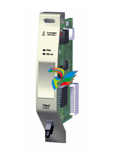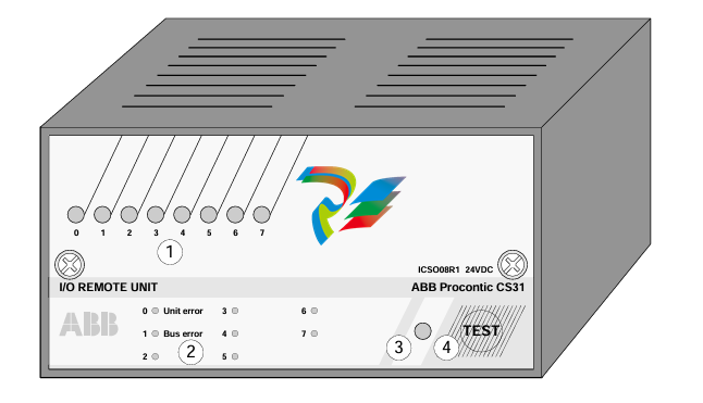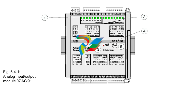
The module performs internal diagnostics at both levels, and
immediately indicates detected error conditions with either of its status
LED indicators. When a status LED indicator is continuously ON, the status is OK.
Module Diagnostics When Cycling Power
When you cycle the module’s power, the module performs a series of
internal diagnostic tests. If the module detects a failure, its module
status LED indicator remains off.Channel Diagnostics
When a channel is enabled, the module checks for a valid
configuration. Then on each scan of its inputs, the module checks for
out-of-range and open-circuit fault conditions of its inputs including the CJC thermistor.

When the module detects a failure of any channel diagnostic test, it
causes the channel status LED indicator to blink and sets the
corresponding channel fault bit (bits 12…15 of the channel status
word). Channel fault bits and LED indicators are self-clearing when
fault conditions are corrected.
IMPORTANT:If you clear the channel enable bit, channel status bits are reset.
Module and Channel Diagnostics
The module operates at two levels.
• Module level
• Channel level
Module level operation includes functions such as cycling power,
configuration, and communication with the SLC processor. ON
indicates the module is OK. OFF indicates a fault.
Channel level operation includes functions such as data conversion
and open-circuit detection. ON indicates the channel is OK. Blinking indicates a fault.

Command Mode Operation All stepper motor operations are performed in command mode.
This mode is entered by setting the mode flag (bit 15 in output word 0) to 0.
In command mode, the SLC Processor can issue commands and activate different operations or moves. The actions you can command are:
• Absolute Moves
• Relative Moves
• Hold Moves
• Resume Moves
• Immediate Stop Operations
• Homing Operations
• Jogging Operations
• Blend Moves
• Preset Operations
• Reset Errors
Diagnostic Mode
Use the configuration mode to select the diagnostic mode of operation. Once selected,
the diagnostic mode allows you to test your program and wiring by connecting the loop back wires at the
translator. The purpose of loop back diagnostics is to test the system wiring for electrical noise.
The number of pulses received at the feedback should equal the commanded number of pulses at the end of the move.
If they are not equal, the system may be experiencing problems due to electrical noise.
--------------------------------------------------------------------------------------------------------------------------------------------------------------------------------------------------------------
----------------------------------------------------------------------------------------------------------------------------------------------------------------------------------------------------------------------------------------------------------------------------------------------------------------------------------------------------------------------------------------------------------------------------
More Model Recommendations:
1756-OB16IS module Rockwell ControlLogix 16 digital output
1756-OB32 module Rockwell ControlLogix 32 digital output
1756-OB8 module Rockwell ControlLogix 8 digital output
1756-OB8EI module Rockwell ControlLogix 8 digital output
1756-OB8I module Rockwell ControlLogix 8 digital output
1756-OC8 module Rockwell ControlLogix 8 digital output
1756-PA72 Module Rockwell ControlLogix AC Power Supply
1756-PA75 Module Rockwell ControlLogix AC Power Supply
1756-PA75R Module Rockwell ControlLogix AC Power Supply
1756-PAR2 Module Rockwell ControlLogix AC Power Supply
1756-PAXT Module Rockwell ControlLogix XT Power Supply
1756-PB72 Module Rockwell ControlLogix DC Power Supply
1756-PB75 Module Rockwell ControlLogix DC Power Supply
1756-PB75R Module Rockwell ControlLogix DC Power Supply
1756-OV16E module Rockwell ControlLogix 16 digital output
1756-OV32E module Rockwell ControlLogix 32 digital output
1756-OW16I module Rockwell ControlLogix 16 digital output
1756-OX8I module Rockwell ControlLogix 8 digital output
1756-PBR2 Module Rockwell ControlLogix Power Supply
1756-PBXT Module Rockwell ControlLogix XT Power Supply
1756-PC75 Module Rockwell ControlLogix DC Power Supply
1756-PH75 Module Rockwell ControlLogix DC Power Supply
1756-PSCA2 Module Rockwell ControlLogix Adapter
1756-OF4 module Rockwell ControlLogix 4 analog
1756-OF6CI module Rockwell ControlLogix 6 analog
1756-OF6VI module Rockwell ControlLogix 6 analog
1756-OF8 module Rockwell ControlLogix 8 analog
1756-OF8H module Rockwell ControlLogix 8 analog
1756-OG16 module Rockwell ControlLogix 16 digital output
1756-OH8I module Rockwell ControlLogix 8 digital output
1756-ON8 module Rockwell ControlLogix 8 digital output
| User name | Member Level | Quantity | Specification | Purchase Date |
|---|


