DCS; Industrial control system
Product
Article
NameDescriptionContent
Argument
Current Location:
PRODUCT SHOW
Description
Redundant ControlNet to FOUNDATION Fieldbus H1 Linking Device: A Detailed Description
1. Introduction
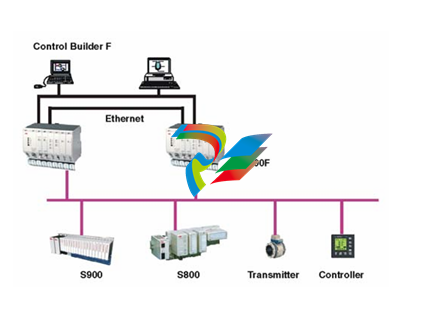
The Redundant ControlNet to FOUNDATION Fieldbus H1 Linking Device is a crucial component in industrial automation systems, specifically designed to bridge the communication gap between ControlNet and FOUNDATION Fieldbus H1 networks. It plays a vital role in ensuring reliable and seamless data exchange between different parts of an industrial process, enhancing system availability and facilitating efficient operation, especially in applications where continuous operation and redundancy are of utmost importance.
2. Physical Design and Construction
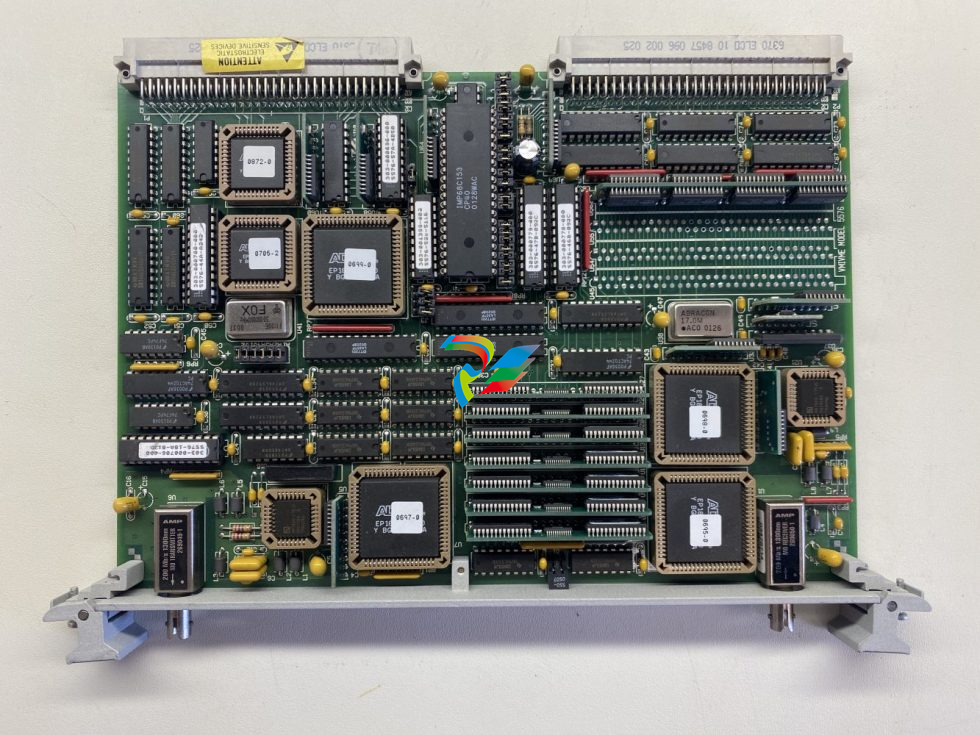
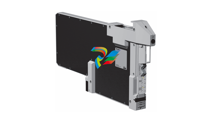
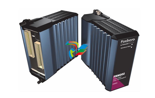
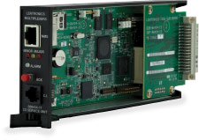
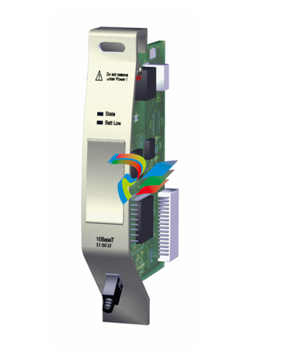
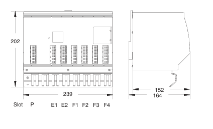
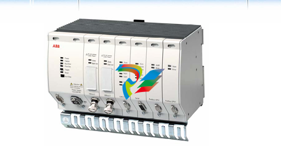
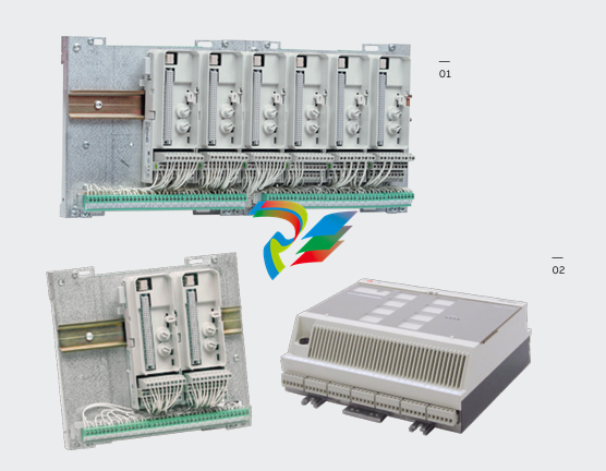
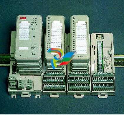
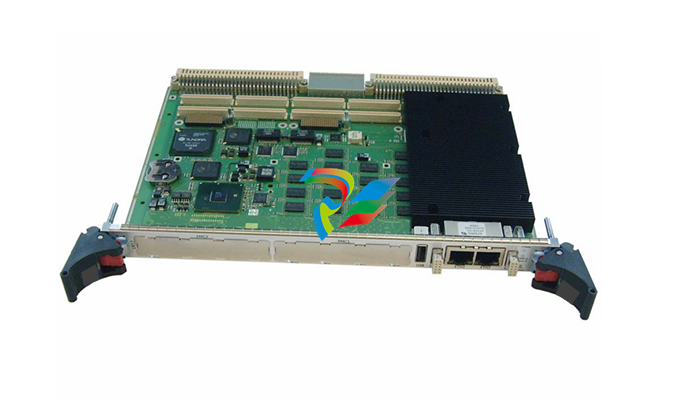
- Compact and Rugged Enclosure: These linking devices typically feature a compact form factor that allows for easy installation within industrial control cabinets or other space-constrained areas. Despite their relatively small size, they are built with rugged materials, such as high-strength metal alloys or durable plastics, to withstand the harsh environmental conditions commonly found in industrial settings. This includes protection against dust, vibration, temperature variations, and electromagnetic interference, ensuring long-term reliability and stable performance.
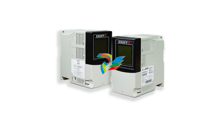
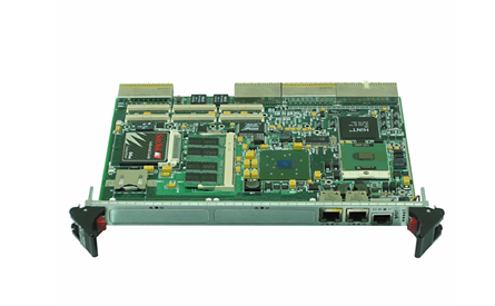
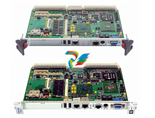
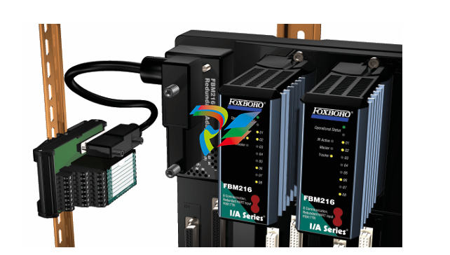
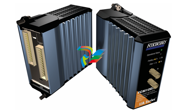
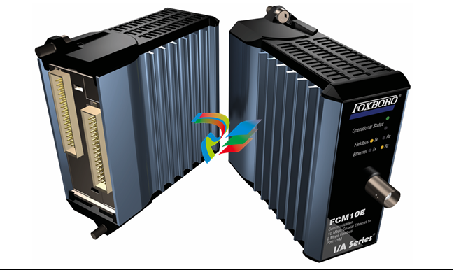
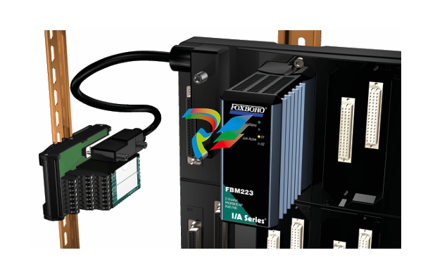
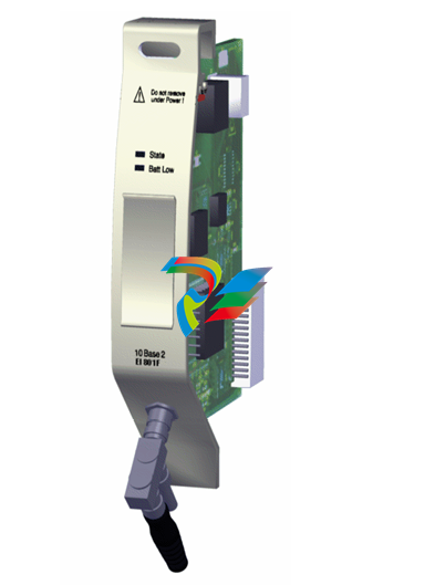
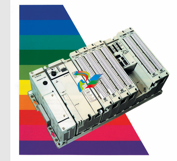
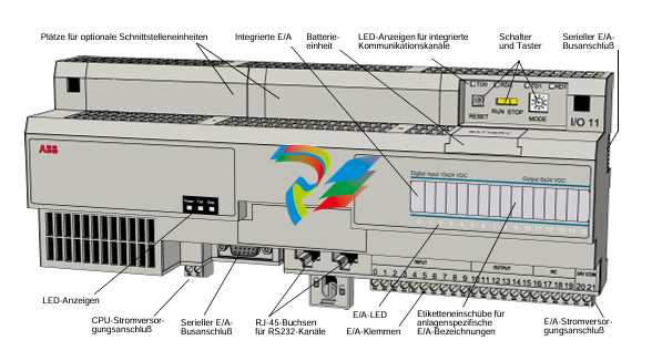
- Connection Interfaces: The device is equipped with a variety of connection interfaces. On the ControlNet side, it has ports that comply with the ControlNet standard, usually in the form of coaxial connectors or specialized network interface ports, depending on the specific implementation. These ports enable it to connect to ControlNet-enabled devices like programmable logic controllers (PLCs), human-machine interfaces (HMIs), or other networked equipment operating on the ControlNet network. On the FOUNDATION Fieldbus H1 side, there are connectors designed to interface with Fieldbus H1-compatible devices, including sensors, actuators, and other intelligent field devices. These interfaces are carefully engineered to ensure proper signal transmission and connection integrity between the two different network types.
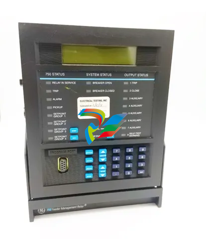
- Redundancy Indicators and Components: To support the redundant functionality, the device often incorporates visible indicators that display the status of the redundant links, such as which link is active and whether there are any issues or failures in the backup link. Internally, it may have redundant power supplies, redundant communication modules, or other components that are designed to take over in case of a primary component failure. This redundancy setup is crucial for minimizing downtime and maintaining continuous communication between the ControlNet and FOUNDATION Fieldbus H1 segments of the automation system.
3. Communication Protocol Conversion
- ControlNet and FOUNDATION Fieldbus H1 Compatibility: The primary function of this linking device is to translate and transfer data between the ControlNet and FOUNDATION Fieldbus H1 protocols. It has a deep understanding of the specific communication rules, message formats, and addressing schemes of both protocols. On the ControlNet side, it can handle various services such as cyclic and acyclic data exchange, which are essential for real-time control and configuration purposes. Similarly, on the FOUNDATION Fieldbus H1 side, it is capable of interacting with field devices following the Fieldbus H1 communication model, including features like device configuration, process variable transmission, and diagnostic information exchange.
- Data Mapping and Transformation: The device performs complex data mapping and transformation operations to ensure accurate conveyance of information between the two networks. For example, data received from a FOUNDATION Fieldbus H1 sensor, such as a temperature reading or a pressure value, needs to be appropriately formatted and mapped into the ControlNet data structure before being sent to a ControlNet-based control system for further processing. Conversely, control commands or configuration data from a ControlNet device are converted into the FOUNDATION Fieldbus H1-compatible format and forwarded to the relevant Fieldbus H1 actuators or devices. This mapping process takes into account factors like data types, scaling, and addressing to maintain data integrity and compatibility across the different network environments.
- Protocol Conversion Logic: Inside the linking device, there is sophisticated protocol conversion logic implemented, which may be a combination of hardware-based processing and software algorithms. This logic continuously monitors the communication on both sides, manages the flow of data, and makes necessary adjustments to ensure seamless and efficient protocol conversion. It also handles issues like data buffering, error detection and correction, and synchronization between the two networks to prevent data loss or corruption during the translation process.
4. Redundancy Features
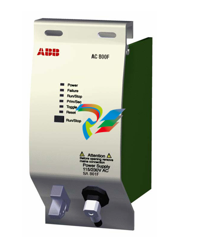
- Redundant Power Supply: One of the key redundancy features is the inclusion of redundant power supplies. In case the primary power source fails, the backup power supply automatically takes over to keep the device operational. This ensures that the communication between ControlNet and FOUNDATION Fieldbus H1 is not interrupted due to power outages or power supply malfunctions. The power supplies are often designed to be hot-swappable, allowing for easy replacement without shutting down the device or affecting the overall system operation.
- Redundant Communication Paths: The device provides redundant communication paths between the two networks. If the primary connection link between ControlNet and FOUNDATION Fieldbus H1 experiences a failure, whether due to cable damage, network interface card issues, or other reasons, the device can quickly switch to the backup communication path. This switchover is typically automatic and occurs within a very short time frame to minimize any disruption to the data flow and the industrial process being controlled. The redundant paths are constantly monitored for their health and performance, and any issues are immediately reported to the system operators.
- Fault Tolerance and Recovery: In the event of a component failure within the linking device itself, it has built-in fault tolerance mechanisms. For example, if a communication module fails, the redundant module can take over its functions seamlessly. The device also has the ability to recover from temporary failures or glitches, such as network congestion or short-term communication errors. It can automatically re-establish proper communication links and resume normal data exchange once the issue is resolved, ensuring that the overall automation system remains operational with minimal impact on productivity.
Purchase history
| User name | Member Level | Quantity | Specification | Purchase Date |
|---|
Total 0 Record
Customer Reviews
Satisfaction :
5 Stars
No evaluation information


