
Part Number IS200FOSAG1A Manufacturer General Electric Country of Manufacture As Per GE Manufacturing Policy Series Mark VI/VIe Function Module Availability In StockIS200FOSAG1A is a fiber optic interface board designed and developed by GE. It is a part of the GE drive control system. FOSA is mounted within the control assembly backplane. This board is frequently used in low voltage Innovation Series AC Drives. Typically, the FOSA is linked to a CABP Control Assembly Backplane. This is a wiring board that connects wiring boards that are interfaced with external signals. Its positioning within the CABP designates it as a pivotal backplane connector, effectively establishing a bridge between components. Notably, this versatile model extends its functionality beyond the CABP to find a crucial role within the control cabinet of a 2300 V Drive. Fiber Optic Interface Board Connectivity The Fiber Optic Interface Board boasts a deliberately minimalist front faceplate design, characterized by the absence of LED indicators. This meticulous design choice is not just an aesthetic consideration; rather, it serves a functional purpose by promoting intuitive identification and facilitating a smooth integration process within the system. In the ever-evolving landscape of the Mark VIe system, this board assumes a pivotal role, especially in the context of its connectivity. As part of its testing procedures, the board undergoes a critical fiber optic assessment. This evaluation is indispensable, given its interconnected nature with another integral component of the system - the IGBT gate driver board. The thorough fiber optic tests are designed to ensure a robust and secure connection between these two boards, contributing significantly to the enhancement of communication efficiency and overall system performance. By subjecting the Fiber Optic Interface Board to rigorous testing, the system not only validates the integrity of the connection but also establishes a foundation for reliability. This emphasis on robust fiber optic connectivity goes beyond mere functionality; it becomes a cornerstone for seamless communication within the system, ultimately elevating the performance and dependability of the Mark VIe system as a whole.
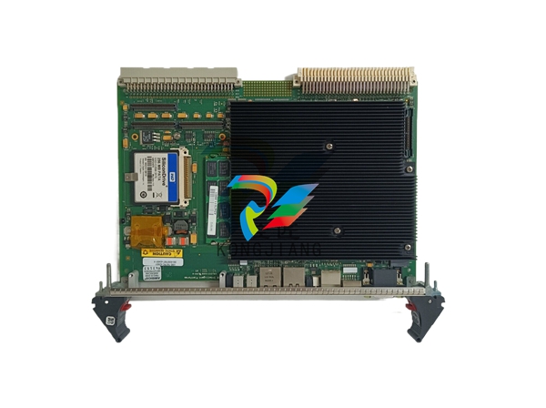
Versatility in Application and Fault Handling Hailing from the domain of GE's drive control system, it serves as a versatile element within low voltage Innovation Series AC Drives. It is commonly associated with the CABP Control Assembly Backplane, a conduit connecting wiring boards that interface with external signals. While offering enhanced capabilities, the board also exhibits a potential to detect and manage faults, including the IGDM DB1 card fit trip fault, further enhancing system reliability. Empowering Control Systems with Innovation The Fiber Optic Interface Board provides reliability and efficiency within control systems. With an ingenious design, adept fiber optic testing capabilities, and comprehensive manual support, this board unlocks new potentials within your control assembly and drive systems. Delve into its attributes to experience unparalleled control system optimization. Features The board is meticulously designed for seamless integration onto the Control Assembly Backplane (CABP), serving as a critical backplane connector that plays a pivotal role within the CABP infrastructure. Its versatility extends beyond the CABP as it is also employed in the control cabinet of a 2300 V Drive, showcasing its adaptability across various applications. An integral part of the system, the module undergoes a crucial fiber optic test due to its connection to another board within the setup. This meticulous testing procedure ensures the reliability and security of the fiber optic connection between the Fiber Optic Switch Assembly (FOSA) and the corresponding Insulated Gate Bipolar Transistor (IGBT) gate driver board. The validation of the fiber optic connection is paramount, as it guarantees flawless communication and optimal performance between the interconnected boards, contributing to the overall efficiency of the system. For comprehensive insights into the board and its functionalities, the GEI-100270 Control Assembly Backplane Board Manual stands as the go-to resource. This manual not only serves as a guide for the Fiber Optic Switch Assembly (FOSA) board's installation but also offers essential instructions for its operation and maintenance, providing users with detailed information to ensure the smooth functioning and longevity of the board within the larger system. Product Attributes Reliable and High-Speed Communication: Designed to ensure reliable and high-speed communication between different components of the control system. It utilizes fiber optic technology, which offers advantages such as low signal loss, immunity to electromagnetic interference, and high data transmission rates. By leveraging fiber optic communication, the board enables efficient and secure data transfer between modules, including the main processor, input/output modules, and other control system components. Multiple Fiber Optic Ports: Features multiple fiber optic ports, allowing for multiple connections and communication channels between various components of the control system. These ports provide the flexibility to establish simultaneous communication links, facilitating data exchange and synchronization between different modules. The multiple ports enable efficient and robust communication architecture within the control system. Diagnostic Capabilities: Equipped with diagnostic capabilities that enable monitoring and troubleshooting of the system. These diagnostic features provide insights into the performance and status of the communication links, allowing for quick identification and resolution of any issues that may arise. The ability to monitor and diagnose the system ensures smooth operation and minimizes downtime. Harsh Environment Durability: Designed for use in harsh environments, the board is built to withstand challenging conditions commonly encountered in turbine control systems. It is engineered to withstand high temperatures, vibrations, and other environmental factors that could potentially impact its performance and reliability. This durability ensures that the board can operate consistently and reliably, even in demanding operational conditions. Small Footprint Design: Designed with a small footprint, making it suitable for installations where space is limited. The compact size allows for easy integration and installation within control system enclosures or cabinets, even in tight spaces. This design feature provides flexibility in system configuration and simplifies installation processes. High-Speed Communication and Data Transfer: By facilitating high-speed communication and data transfer, the board enables precise control and monitoring of the turbine's operation. The fast and accurate transmission of data between the control system components allows for real-time monitoring, analysis, and adjustment of the turbine's performance. This capability is crucial for ensuring safe and efficient operation, maximizing the turbine's output while maintaining optimal performance and reliability. Board Replacement Procedure Turn Off Power: As a safety measure, the first step is to turn off all power to the drive. This includes shutting down the main power supply and any auxiliary power sources. Once the power is off, wait for several minutes to allow all capacitors in the power supply to discharge fully. This step minimizes the risk of electrical shocks and ensures that the system is safe to work on. Access the Printed Wiring Boards: To access the board that needs replacement, open the cabinet door on the equipment. This will provide access to the printed wiring boards housed within the cabinet. Prepare the Board Carrier: To safely remove the board, locate and pull the lock tabs on either side of the board rack. Then, lift the front board carrier, which holds the drive control card, and gently tilt it forward and down. This action will give you clear access to the board that requires replacement. Disconnect Cables from the Board: With caution, disconnect all cables from the board that needs to be replaced. If the board has ribbon cables, grasp the connector on each side and gently pull it free. For cables with pull-tabs, carefully pull the tab to release the connector. Release the Board from the Carrier: The next step is to release the old board from the board carrier. This can be done by pushing back on the plastic snaps or holders that secure the board in place. Carefully remove the board from its position once it is released from the carrier. Check Jumpers and Switches on the New Board: Before installing the replacement board, double-check that all jumpers and switches on the new board are in the same position as they were on the old board. Ensuring that the settings are identical will help maintain the correct configuration. Install the New Board: Carefully place the new board onto the board carrier, orienting it in the same position as the one removed. Take care to align the connectors properly. Secure the Board: Ensure that all plastic snaps or holders snap back into place, securing the new board on the carrier. Reconnect Cables: Reconnect all cables to the new board in the order they were labeled. Ensure that each cable is properly seated at both ends to establish reliable connections. Adjust EE Parameters: Follow the specified procedure in the EE Parameter Adjustments section (if applicable) to adjust the EE (electrical and electronic) parameters on the new board. This step is crucial to ensure that the drive functions optimally with the replacement board. Return the Front Board Carrier: Carefully return the front board carrier, with the new board installed, to its original position in the cabinet. Slide the lock tab(s) on the board rack's side back into the locking position to secure the carrier in place.FIBER OPTIC I/O
| User name | Member Level | Quantity | Specification | Purchase Date |
|---|


-
 ETEL AccurET MODULAR 300 EA-P2M-300-xxxxxA controller
 -
 Basler Electric ES Series Protection Relays
 -
 ABB Multifunction Protection and Switchbay Control Unit REF542plus
 -
 EMERSON AMS 2140 Machinery Health Analyzer
 -
 Hirschmann Industrial Ethernet Rail Switch RS20 Basic Family
 -
 GE Grid Solutions P40U Px40 USB Adaptor
 -
 ABB ontinuous Gas Analyzers AO2000 Series AO2040CU Ex Central Unit in Category 2G
 -
 ABB Advance Optima AO2000 Series Continuous gas analyzers Models AO2020. AO2040
 -
 Advance Optima Module Uras 14
 -
 SAACKE control optimization
 -
 SAACKE se@vis efficiency monitor
 -
 SAACKE se@vis pro
 -
 SAACKE se@vis eco
 -
 SAACKE se@vis compact
 -
 HIRSCHMANN Industrial ETHERNET Switch MICE MS20/MS30
 -
 HIRSCHMANN MICE Media modules
 -
 Kongsberg GL-10 Level Switch
 -
 B&R ACOPOSinverter P74 frequency converter
 -
 Beckhoff CX2020 | Basic CPU module (service phase)
 -
 Beckhoff CX1010 | Basic CPU module (service phase)
 -
 Beckhoff CX5120 | Embedded PC with Intel Atom® E3815
 -
 Beckhoff CP69xx-xxxx-0010 | Economy built-in Control Panel with DVI/USB Extended interface
 -
 Beckhoff CP29xx-0000 | Multi-touch built-in Control Panel with DVI/USB Extended interface
 -
 SAACKE Monoblock Rotary Cup Burner SKVJ-M
 -
 ABB Plantguard Fault Tolerant Technology Architecture and Software
 -
 OMRON H8PR-8/H8PR-8P H8PR-16/H8PR-16P H8PR-24/H8PR-24P Rotary Positioner
 -
 ABB PFSA107-Z42 DTU Stressometer Digital Transmission Unit
 -
 Nidec Mentor MP
 -
 IBA ibaNet-E
 -
 IBA FO Connection to Reflective Memory
 -
 IBA FO Connection to Siemens Systems
 -
 IBA Interface Cards For Fiber Optic Connections
 -
 IBA Field and Drive Buses
 -
 IBA ibaPADU-S Modular System
 -
 IBA ibaMAQS
 -
 STUCKE SYMAP®ARC
 -
 STUCKE SYMAP®R
 -
 STUCKE SYMAP®Compact
 -
 MOOG G123-825-001 BUFFER AMPLIFIER
 -
 Motorola MVME5100 Series VME Processor Modules
 -
 Motorola MVME162 Embedded Controller
 -
 HIMatrix Safety-Related Controller System Manual for the Modular Systems
 -
 Motorola MVME2400 Series VME Processor Module
 -
 Sieger System 57
 -
 KONGSBERG MRU product line continuation
 -
 Woodward easYgen-3100/3200 Genset Control for Multiple Unit Operation
 -
 Woodward MFR 300 Multifunction Relay / Measuring
 -
 ABB AX410, AX411, AX413, AX416, AX418, AX450, AX455 and AX456 Single and dual input analyzers for low level conductivity
 -
 ABB AX410, AX411, AX416, AX450 and AX455 Single and dual input analyzers
 -
 Woodward easYgen-1400 Technical Manual Genset Control
 -
 Woodward easYgen-400 Operation Manual Genset Control
 -
 Woodward High Output Digital Valve Positioner (DVP)DVP5000/DVP10000/DVP12000
 -
 Woodward High Output Digital Valve Positioner DVP5000 and DVP10000
 -
 Woodward TG611-13/-17 Overspeed Test Device Conversion Kit
 -
 Woodward MicroNet Safety Module (MSM)
 -
 Woodward 2301A Electronic Load Sharing and Speed Control 9905/9907 Series
 -
 Woodward-Service Bulletin 01671
 -
 UniOP eTOP40B 12.1” TFT color display
 -
 UniOP eTOP40 TFT Color display
 -
 UniOP eTOP33B 10.4” TFT color display
 -
 UniOP eTOP33C eTOP33-0050 Resistive touchscreen
 -
UniOP eTOP30. eTOP32 eTOP32-0050 Human-machine interface equipment
-
 UniOP eTOP20B and eTOP21B eTOP20B-0050
 -
 UniOP eTOP12 eTOP12-0050 Advanced human-machine interface equipment
 -
 UniOP eTOP11 eTOP11-0050 HMI
 -
 UniOP eTOP06C HMI
 -
 UniOP eTOP06 HMI
 -
 UniOP eTOP05EB eTOP05EB-DF45 HMI
 -
 UniOP eTOP05. eTOP05P Human-machine interface equipment
 -
 UniOP eTOP03 eTOP03-0046
 -
 UniOP eTOP507 507U2P1 eTOP Series 500 Human-Machine Interface
 -
 UniOP eTOP307
 -
 UniOP ETT-VGA Human-machine interface touch unit
 -
 UniOP ePAD32B, ePAD33B and ePAD33BT ePAD33B-0350
 -
 UniOP ePAD05 and ePAD06
 -
 UniOP CP02R-04 Human-machine interface
 -
 UniOP ERT-16 - Industrial PLC Workstation
 -
 UniOP ePAD03 and ePAD04
 -
 UNIOP EPALM10-DA71 state-of-the-art handheld HMI
 -
 Watlow SERIES CLS200 SPECIFICATION SHEET
 -
 Detailed Explanation of B&R Power Panel 300/400: The Core of Industrial Automation Control
 -
 YOKOGAWA Models ANB10S, ANB10D, ANR10S, ANR10D Node Units (for FIO)
 -
 Woodward ESDR 4 Current Differential Protection Relay
 -
 Woodward easYgen-3000 Genset Control for
 -
 Woodward CPC-II Current-to-Pressure Converter
 -
 Woodward 8290-189-EPG-installation-manual 8290-044
 -
 Woodward Product Change Notification 06946A
 -
 Woodward Product Change Notification 06912
 -
 Fisher™ 4660 High-Low Pressure Pilot
 -
 Flexible digital protection and control equipment SYMAP®
 -
 Woodward 723PLUS Digital Control
 -
 Woodward 505 Digital Controller For steam turbineses
 -
 Woodward 85018V2 505E Digital Governor for Extraction Steam Turbines
 -
Woodward 85018V1 Turbine Control Parameters
-
Woodward 26871 505 Enhanced Digital Control for Steam Turbines
-
 Woodward 03365 505E (Extraction / Admission)
 -
 KONGSBERG RMP420-Remote Multipurpose Input/Output
 -
 KONGSBERG RCU501 Remote Controller Unit
 -
 KONGSBERG RCU500 Remote Controller Unit
 -
 K-Gauge TOP KONGSBERG Tank Overfill Protection SystemFeatures
 -
 Kongsberg DPS112 DGNSS (DGPS/DGLONASS) sensor
 -
 Kongsberg d0000930-presafe-atex-report signed
 -
 HIMax TECHNICAL FACTS X Series
 -
 GE Multilin F650
 -
 GE MIF II - Legacy
 -
 GE PQM II Power QualIty Meter
 -
 Hydran 201Ti Mark IV Essential DGA monitoring for transformers
 -
 alstom AMS42/84 5B Amplifier SystemAmplifier Technology at its Best.
 -
 GE VMIVME-5576 Fiber-Optic Reflective Memory with Interrupts
 -
 GE Multilin 750/760 - Legacy Feeder Protection System
 -
 GE Fanuc Automation VMICPCI-7806 Specifications
 -
 VMIVME-7807 VME-7807RC* Intel® Pentium® M-Based VME SBC
 -
 GE Fanuc Automation VMIVME-7750 Specifications
 -
 FOXBORO Compact FBM240. Redundant with Readback, Discrete
 -
 FOXBORO FBM208/b, Redundant with Readback, 0 to 20 mA I/O Module
 -
 FOXBORO FBM201e Analog Input (0 to 20 mA) Interface Modules
 -
 Foxboro DCS FBM206 Pulse Input Module
 -
 FOXBORO FBM216 HART® Communication Redundant Input Interface Module
 -
 FOXBORO Z-Module Control Processor 270 (ZCP270)
 -
 FOXBORO Fieldbus Communications Module, FCM10Ef
 -
 FOXBORO Fieldbus Communications Module, FCM10E
 -
 Foxboro DCS Compact FBM241/c/d, Redundant, Discrete I/O Modules
 -
Foxboro FBM223 PROFIBUS-DP™ Communication Interface Module
-
 Foxboro DCS FBM204. 0 to 20 mAI/OModule
 -
Foxboro FBM239, Discrete 16DI/16DO Module
-
Foxboro FBM202 Thermocouple/mV Input Module
-
 Foxboro E69F Current-to-Pneumatic Signal Converter
 -
 EMERSON M-series Intrinsically Safe I/O


